Help Reading A Drawing

Pontiac Freak

Active User
Registered
Joined
Nov 9, 2010
Messages
306
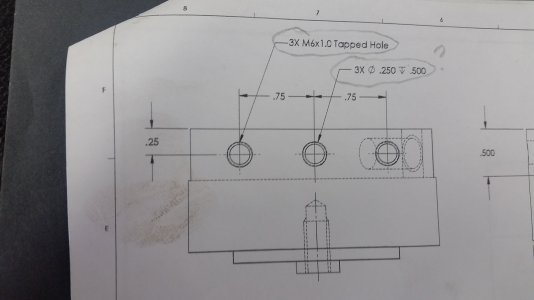
I am reading a drawing but am not sure if I am reading it right. In the picture you will see 2 items circled. The first one shows the bolt size and thread and quantity. The second one I am assuming means 3 holes .250" diameter with a depth of .5" is this correct? Does anybody have a quick easy cheat sheet for symbols?

thx in advance!
 
Those are only a couple of standard GD&T symbols. You can search Google and find whatever depth you desire on learning them. Not all are used all the time, but it pays to be familiar with at least the basic ones if you are machining to a standard manufacturing drawing.
 
What is missing on the drawing is the depth of the tap. It would be represented by the flaccid arrow sign followed by the depth. (same notation as the drill depth). The tap depth spec will determine whether you use a taper, plug, or bottoming tap or if you need to threadmill the hole.
 
Those would be the counter bore for the m6 bolts I do belive
 
Yes, a 6mm tap will clear a quarter inch hole by .014, no threads at all.
 
Like the man said tap depth missing. 3 holes .250 dia by .500 deap. Tbell
 
Sigmetrix_software_GDandT_symbol_Depth.jpgmeans depth. I have never used it in my drafting classes. I had to search Google to find it. Not sure what the designer is having you do. You are drilling and taping then re-drilling the same hole. A three place decimal could be a reamed on size hole as well. There should have been a front view of the drawing showing the holes for clarity.

The Best with your project.
 
Back
Top