Help Needed Wiring In Power Feed On 1964 Bridgeport J Head Table Feed

Mutt

Registered
Registered
Joined
Aug 16, 2014
Messages
366
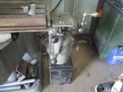
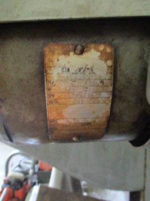
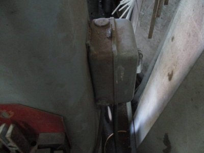
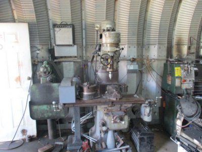
Bought a 1964 Bridgeport J head mill complete with table power feed, vise and super spacer rotary table for a $g. The standard table power feed isn't wired up. Can some one help me connect the wires? Motor is stock 1/8 hp 220v 3 ph.
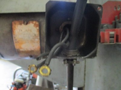
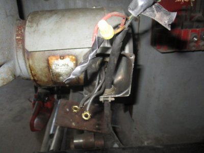
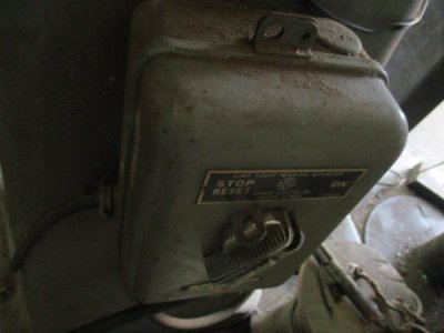
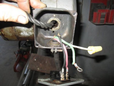
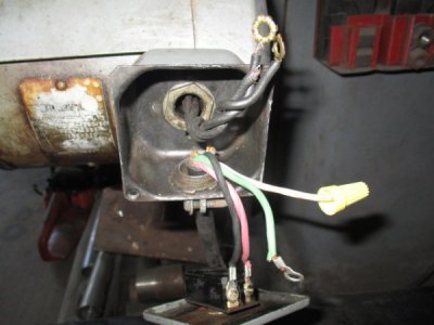
3 leads coming from motor, no tracers or markings on these black wires. A 4 lead wire coming out of the main breaker box / reset on rear of mill (standard 4 wire 3 ph red/black/white/green)
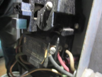
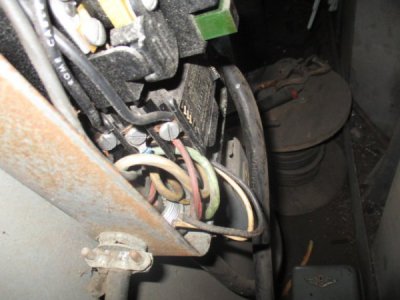
Last pic on left is the 3 leads from the motor, last right is the 4 lead cable coming from the breaker box on back of the mill
IMG_3291.JPG
IMG_3292.JPG IMG_3286.JPG IMG_3288.JPG
IMG_3287.JPG IMG_3290.JPG
IMG_3289.JPG IMG_3285.JPG
 
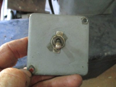
I think you can safely assume that the 3 motor leads are connected to a motor starter in the panel. The toggle switch would control the motor starter.

A picture of the inside of the control box would be helpful.

Do you have 3 phase power in your shop?
 
I have a static 3 phase converter hooked up. Mill runs forwards and reverse. The 3 black leads come straight out the side of the
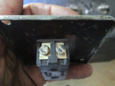
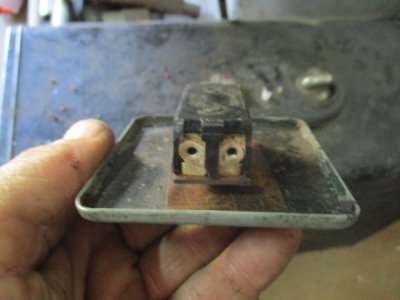
electric motor on the power feed itself. The 4 lead cable comes out of a "reset" box on back of the mill. Looks factory to me. Here's some other pics The red and black wires were hooked up to the on/off switch when I got it.
IMG_3316.JPG IMG_3317.JPG IMG_3318.JPG IMG_3319.JPG IMG_3320.JPG
 
Yeah,...... that doesn't look right. :cautious:

The Green wire should be Ground, the Black, Red, and White wires should connect to the motor wires. I would expect the switch to have 6 terminal screws, one pair for each of the 3 hot legs, one side to power and the other side to the motor wires. Maybe the original switch was replaced by someone who was less than skilled in the art.:confused: Theoretically you could use a Double Pole switch to turn a small 3 phase motor on and off, and just leave one leg connected, but it would leave one leg hot all the time, not a safe condition IMHO.

You need to take a look at the other end of that cord to see what it's wired to.
 
Ok, here's the motor controller
right side looking at it has the 4 wire lead from the converter, green ground, black/white/red to terminals on right side

left side has the 4 wires hooked to the left side terminals and the green to ground, also the 3 wires to the power feed and the green to ground. All 3 leads to the power feed read 125v each, green reads ground

IMG_3361.JPG IMG_3363.JPG
 
I see what appears to be a motor starter in there, does that connect to the spindle motor also?
 
Yes, spindle wires run from the switch's left side up to the drum switch on the top of the mill head
 
I can't see enough of the box on the back of the mill to figure out exactly what it is. It may be just an overload and switch for the motors. There does not seem to be any way of operating a motor starter.

Bottom line is that the 3 feed motor wires should connect to the Black, White, and Red wires, preferably through a switch. Green should be connected to the motor frame.

Given that you are using a static phase converter to run the spindle and if you want to run the power feed without the spindle running, I would concider a small VFD to run the power feed motor. Something like this one:

https://www.automationdirect.com/ad...l)/GS1_Drive_Units_(120_-z-_230_VAC)/GS1-10P2

Because if the power feed motor is started on the static phase converter without the spindle running the spindle may not start because the static phase converter has already dropped out.
 
Back
Top