- Joined
- Dec 26, 2016
- Messages
- 2,081
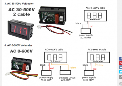
I have a 20 amp variac that came with an anolog voltage display, I thought it was an easy task to replace it with a digital one so I ordered the proper size display units (two of them) one came with just two wires and according to the listing it does not need its own power supply, that sentence got me really confused because there's another display that has 3 wires which I also ordered ,the third (yellow) wire can be connected to its own power supply.
What concerns me is the two wire voltmeter(AC 30-500V) would start powering up at about 30 volts and my concern is it would dim bellow 30 volts, that's why I also ordered the 3 wire meter(AC 0-600V) I took a screenshot of how to connect both.
My question is, do I need a dedicated power supply so the display could show all the way to zero? or is it possible to get the power from the ON/OFF power switch to connect to yellow but don't I need a "load" or return (don't know how the pros say it) to connect to the black wire?
In the comment section of the video someone commented:
You can usually mod the two-wire devices to three wire and run the power to the module from the line. This means good brightness across the board and voltage measurement down to a few volts. As you have an autotransformer variac, there's no issue taking the supply to the module from the primary and the sense voltage from the secondary.
Here's another question, can any of you guys explain this in simple trems so some like me could understand, please., I'll get it . someone made a video of doing the very same upgrade but with a two wire module and you'll know what I'm talking about once you watch it:


 I mislead you, ignore my last comment. The black wire will go to the neutral white wire or blue wire on the switch. The red will go the brown fuse side that goes to the variac. The yellow will go to red wire side of the plug-in. Again, looking at the first schematic on the 4. ac 0-600 volts according to the specs, it should work just fine on 110 ac.