[Metrology] Haimer 3d NG Probe Offset Issue

GingerMidget

Registered
Registered
Joined
Apr 11, 2022
Messages
16
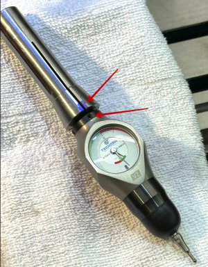
So I decided to go with a new Haimer 3D probe for my PM-728 edge locating duties.
My first use I did not give any thought to the centering and just used it as intended - put it in an ER32 12mm collet, chucked it up and then went about setting zero points in the x & y axis.

Problem is that I found after drilling a few holes that it seemed like my holes were off a bit. Turns out the probe's dial face reads zero at 12 o'clock and 6 o'clock like its supposed to but the edge is like 0.02 something off from the actual edge.

I confirmed this "not my true zero offset" via using a 5/16" ground pin in a 5/16" ER32 collet and low and behold the Haimer is not setting zero like it should.

I measured the ball and its the correct size per the instruction sheet. The short probe is the factory probe and I even have the long probe and that ball is the correct size.

Am I doing something wrong or is the Haimer 3D probe damaged in some way?

No way am I dropping the kind of cash you shell out for a Haimer to have this happen. The gauge is pristine - no damage and used like 3 times until I noticed the error.

Thoughts?
 
The problem with any type of probe which mounts in the spindle is that you can have runout in the mount. The Haimer and similar types have mechanisms to zero that runout out so the probe tip is concentric with the axis of rotation. More seriously, though, the runout can vary each time you use the probe unless you take steps to correct/prevent it. That is the reason I use the old fashioned edge finder as, by nature, it is always concentric with the spindle axis. That is also true for the wiggler.

Some time ago, I made a spindle mounted microscope for my mills. The microscope is mounted in its own dedicated R8 end mill holder. For the Tormach, I can precisely lock the spindle in the same position each time. With a centering adjustment, I thought that I had the runout issue licked but found to my disappointment, that I did not. Granted, I am looking variations measured in tenths, but for precise work, I still have to recenter the microscope each time I use it.
 
I never heard of this device before, it may be just fine, just the thing in some situations, but I'd have to agree with RJ, I'll stick with my wiggler or edge finder.
 
What RJ said. The first time you use it adjust the 4 set screws near the top of the unit to get it concentric w/ the spindle (use a test indicator on the probe tip). I personally wouldn't expect to have to recalibrate on each use, but depends on your accuracy requirements.

@RJSakowski - what sort of deviation do you see in your spindle-mounted microscope when removing and re-installing? Typically under 1 thou?
The microscope can easily resolve a tenth. When I tried to make a cross by dragging a fresh razor blade across a block of aluminum, it looked like I dug a trench with a backhoe. @JimDawson wrote some software that includes software crosshairs that works well. I align the microscope by centering on a target and rotating the spindle. I then move the crosshairs to the center of rotation and recheck. I am centered when the crosshairs stay centered on the target as I rotate.

It has been a while since I last used the microscope but I believe that the deviation upon removal and reinstallation is around a thou or less. I suspect that this is mostly due to the R8 socket on my Tormach mill. A better fit should result in a repeatable positioning.
 
I have both the Haimer and an optical center. Both work great.
The Heimer is supposed to come from the factory correctly adjusted but it can be off. The included instructions tell you how to recalibrate it. You do not have to do it very often but you should check it if you over travel the tip. Each time you install a new tip you should recalibrate it. I am on my 4th tip! I have yet to break the optical center....


Per what Robert and others indicated, my Haimer was not aligned when I purchased it and also needs to be re-centered if you change the tip. In addition you will find that you need a test indicator that measures down to 0.0001" in order to get it to repeat correctly, and also using a high quality ER32 holder and collet. The tips are also very fragile, and I would recommend getting a backup. I seem to break one every couple of months and some replacement tips I bought from Amazon and they must have been from the reject pile as there was not enough adjustment to get them on center. The last two I purchased from MSC.


Attachments

  • Haimer Universal 3D-Sensor manual.pdf
    297 KB · Views: 7
Unless you properly calibrate your 3D probe, you are not going to achieve accurate edge-finding results. It's also critical to do as much as possible to ensure the probe is mounted into the mill spindle in the same orientation and with the same tool holder each time. For instance, I have both a Haimer and a Tschorn 3D probe - they are functionally similar. Shown below is my Tschorn 3D Tester SLIMplus V2 and the Lyndex R8 collet that is always (only) used with the 3D indicator, and the collet is marked such that that probe and the clocked position of the collet in the R8 spindle are always aligned. This works to eliminate variations in accuracy when the probe is taken out and put back into the spindle. Note the blue marking on the colllet and how that aligns with the adjusting screw on the probe - my spindle has a similar marking for consistent alignment of the collet.

3D Surface Indicators - 1a.jpg

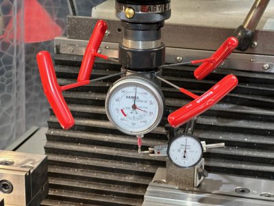
I will re-align the probe on both my Haimer and the Tschorn every month, when I install a new probe, or I find some kind of tolerance discrepancy on a machined part. Shown below is the setup I use to calibrate the probe. My Haimer is mounted to an ER32 collet chuck and remains in that tool holder and clocked to the spindle in the same manner consistently. Others here employ a dedicated R8 end mill holder for their Haimers.

I have found it enormously helpful when dialing in the probe to have four (4) separate T-handled hex-keys that remain in the four alignment set screws throughout the alignment process. The adjustment points are fiddly to keep trying to get your Allen key in them again and again.

3D Surface Indicators - 1 (1).jpeg

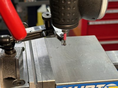
The indicator shown in that setup is a tenths indicator and the stylus is centered on the back of the probe tip and aligned vertically as you can see below. The calibration process is very similar to how you would align the OD of a cylinder in a 4-jaw independent chuck on the lathe. Concentrate on two opposing adjustment screws, getting that "axis" aligned (same indicator reading when the spindle is rotated 180 degrees), before moving on to the alternate axis. Back and forth until rotating the spindle produces zero variation on the indicator touching the probe. It can be tedious getting used to it, and try your best to get the same amount of torque applied to each of the four adjusting set screws. Caution on over-torquing the adjustment screws.

3D Surface Indicators - 1 (2).jpeg

I actually prefer the Tschorn over the Haimer for a few reasons.
  1. If you ever crash the 3D indicator body into the side of a chuck and it needs repair, Haimer will charge more for the repair (sending it back to Germany) than the cost of buying a new unit. Tschorn in the USA has a fixed rate swap-out policy that costs about half what a new unit costs - you send them the damaged unit, they send you a replacement within a couple of days.
  2. The Tschorn probe is a bit more robust and tolerant of abuse than the Haimer probes in my experience.
  3. The 3D indicator body is more compact and can reach into tighter spaces.
  4. And the Tschorn is a lot less "twitchy" if you're running the probe along the top surface of a part to check flatness.
Hope this helps.
 
Last edited:
Please turn the spindle on with those keys in place!
Good info about clocking the toolholder. I have not done that. I use a 12mm R8 collet. I am usually OK with 1-2 thou for my projects.
 
Last edited:
The problem with any type of probe which mounts in the spindle is that you can have runout in the mount. The Haimer and similar types have mechanisms to zero that runout out so the probe tip is concentric with the axis of rotation. More seriously, though, the runout can vary each time you use the probe unless you take steps to correct/prevent it. That is the reason I use the old fashioned edge finder as, by nature, it is always concentric with the spindle axis. That is also true for the wiggler.

Some time ago, I made a spindle mounted microscope for my mills. The microscope is mounted in its own dedicated R8 end mill holder. For the Tormach, I can precisely lock the spindle in the same position each time. With a centering adjustment, I thought that I had the runout issue licked but found to my disappointment, that I did not. Granted, I am looking variations measured in tenths, but for precise work, I still have to recenter the microscope each time I use itw

When I received the 3D probe I went through checking the runout on the gauge. First, for the sake of confirmation, I checked the runout on my spindle: <= 0.0005" per my Mitutoyo, then the Tormach ER32 collet holder mounted in the TTS R8 collet: ~0.0005"+/- 0.0001", and finally the runout on a 5/16" ground pin, and again like 0.0005" - perfectly acceptable.

Next I mounted the Haimer 3D in a 12mm ER32 collet and secured it in the mill spindle. From here I set up my Mitutoyo dial test gauge to verify concentricity of the probe ball. Out of the box the H3D was very close but I went through the steps to get it at most 0.0003" to 0.0005" out. I checked the adjustment screws for tightness, verified nothing moved, and said that it was concentric in this set up. I then took the 3D probe out of the collet, tuned the spindle 180 degrees, remounted the 3D probe and checked for any changes. Happy with the fact nothing changed I moved on.
So now I can say this: the spindle and ER32 holder and collet are not imparting any significant runout and the gauge ball is concentric.
I double checked myself last night just to be sure. After setting up the Haimer and fining x & y zero's on a clean milled aluminum bar, as soon as I place my 5/16" test pin in and check its offset, I get an error of .018-.020 out from the true edge.

Haimer does not say you must reset the concentricity every time you use it, if that were the case I would have never purchased it.
It does say that once you set concentricity you are good to go and may even change tips without effecting the accuracy. Unless I am reading the instructions wrong, or misunderstanding them, then I cannot see how my setup can produce a discrepancy/runout 40 times larger than what I am seeing as my actual runout.
 
Back
Top