Gold Mine or a Bust?

SHop Apprentice

Registered
Registered
Joined
May 26, 2017
Messages
21
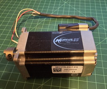
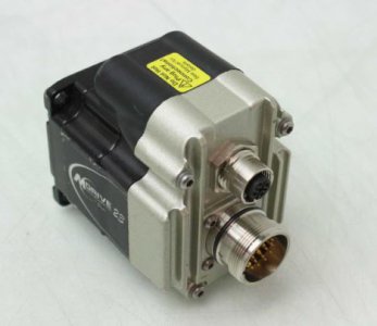
My buddy went to a sale and picked up 7 Stepper? motors and some other stuff for $40. They look like they have internal encoders and controllers. I was thrilled to pay him for the treasures as they looked promising. Per usual, they were not stored well. I think they were put in a coffee can and shaken once a month. Let's say no attempt to preserve them or protect them from moisture.

Off to the internet to see what we can learn.
The company that made them, Intelligent Motion Systems, is no longer viable and has been bought out twice from what I can tell.
Built-in controllers made them special.
The motors are designed for Windows XP
The Windows XP software site is no longer active.
Newer software may work for a newer version of this motor/servo/stepper.
The motors are sealed? - that is good if true.
They use step and direction for inputs - Widely believed to be true but only one version does.
  • Step and direction
  • RS422 or RS485
  • SPI
  • ModBus
  • Ethernet
  • CANopen

Models include
  • Mdrive Plus
  • Mdrive Plus2
  • Mdrive Plus-65 - this is the sealed version

Options include
  • Internal Magnetic Encoder for Closed Loop Control
  • Integrated Planetary Gearbox
  • Control Knob for Manual Positioning
  • Linear Slide
Built in controller!

Three Rotary Motor Lengths Available


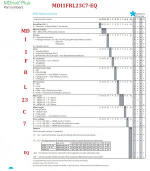
I break down my model number: MDI1FRL23C7-EQ
  • MD Mdrive
  • I Version: Intelligent controller RS422-485
  • 1 Input: Standard input
  • F P1 connector: Flying leads
  • R Protocol: RS422-485
  • L P2 Connector: Wire Crimp
  • 23 Size: Nema23
  • C Motor Length: Triple stack
  • 7 Voltage: 12-73v
  • EQ Options: Internal magnetic encoder with 512 Lines
Okay, this is what I have:
An older motor
Does not use Step and Direction
Uses an archaic terminal program utilizing RS422/485
Not interfaceable with Mach3 or other software (that I can find)

That was fun but no joy. There is no gold in this pan! All bad news? No, lots of parts, switches, bearings and stuff that will likely be useful, well worth the $40.

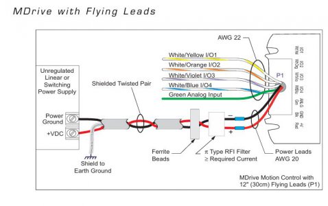
My one unanswered question is this: All the motors are using 3 wires to power and control. There is positive voltage in, a ground and a single I/O line. If anyone knows what this represents, let me know. RS485 has two data lines and when you add that to the required positive and negative power lines, I come up with four wires minimum, unless they are using the ground as a data line.

My goal is to get at least one thread on this website that talks about MDrive motors.
 

Attachments

  • 20241117_205001.jpg
    20241117_205001.jpg
    416.8 KB · Views: 25
  • PartNumber.jpg
    PartNumber.jpg
    110.7 KB · Views: 25
  • mdrive23.pdf
    mdrive23.pdf
    263.2 KB · Views: 5
Last edited:
You should be able to run the serial control with an STM32 / auduino type of thing , might need a 422/485 line driver chip.

Might be good for any projects requiring positioning or accurate speed control.

Stu
 
I used to use a lot of MDrives at work, very surprised to hear they're no longer viable. I don't recall ever seeing one with only 3 wires, even your picture seems to show more.

You can use RS-485 from many terminal emulator programs, you don't need anything special from IMS (and their program was never very good).

The real 'power' of the MDrive motors was that they have their own internal memory and a couple of GPIO. You could write programs in their sorta-like-assembly language and the motor could run from just power with no additional controllers, drivers, or anything else. Great for simple automation tasks.

GsT
 
You should be able to run the serial control with an STM32 / auduino type of thing , might need a 422/485 line driver chip.

Might be good for any projects requiring positioning or accurate speed control.

Stu
Thanks Stu,
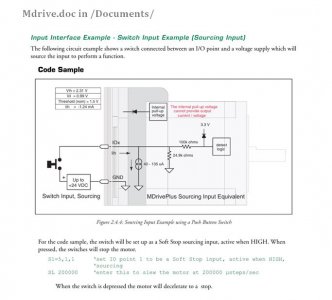
I found the following (attached). The controllers can be utilized for just that purpose. I thinking a 4 or 6 position tool holder for a lathe using a push button to advance to the next position. As GeneT45 points out, they do have their own internal memory.
Thanks for looking at the post.
 

Attachments

  • Stu.JPG
    Stu.JPG
    48.7 KB · Views: 3
I used to use a lot of MDrives at work, very surprised to hear they're no longer viable. I don't recall ever seeing one with only 3 wires, even your picture seems to show more.

You can use RS-485 from many terminal emulator programs, you don't need anything special from IMS (and their program was never very good).

The real 'power' of the MDrive motors was that they have their own internal memory and a couple of GPIO. You could write programs in their sorta-like-assembly language and the motor could run from just power with no additional controllers, drivers, or anything else. Great for simple automation tasks.

GsT
Hi Gene,
All the wires are in the flying leads yet they are all bound and terminated in the cable wrap leaving only 3 wires that were being used: Black - Ground, Red -V+ and White/Yellow - I/O number 1. My thought was: these motors already are programmed so I powered one up. Then I both grounded the I/O line and put it to power thinking the stepper will do it's thing. It did not.

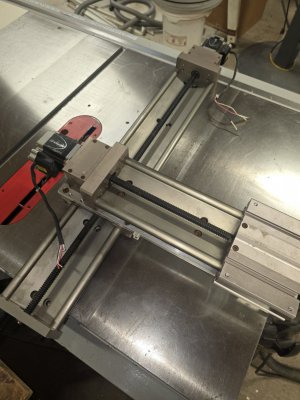
Two of the motors came attached to an XY gantry. Here again, only three wires are terminated and exit the cable bundle.

To your point, there is a new IMS program, as Novantaims still makes a version of this motor.


Thanks for the response.
Bob
 

Attachments

  • Gene.JPG
    Gene.JPG
    53.9 KB · Views: 5
  • Gene2.JPG
    Gene2.JPG
    22.1 KB · Views: 5
I would have expected it to "do its thing" as well, although I recall some of the earlier units could mysteriously lose their program, so that's a possibility. It's also possible that they are fried one way or another. There were several generations, and I think the circular connectors were just an option, not really a generational difference.

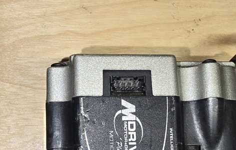
The units I used (it's coming back to me...) had a push to connect header for power and I/O and a dedicated programming cable with a 2-row header that plugged into the top of the motor exclusively for programming. I used a USB or maybe serial to RS-485 to program the motors (we purchased all our MDrives and parts through Olympus Controls in WA. I don't know if they still support MDrives, but you might be able to get a cable from them.) Do0 your motors have a little 8 or 10 pin (I don't recall which it was) header? Should be male pins, but recessed into the body of the motor, IIRC.

GsT
I have 6 others with 3 wires used, I'll try some of the others to see if one of the other motors is still programmed.

The other connector is the P2 connector. (Gene3.jpg) If you look at my image PartNumber.jpg, one of the characters of the serial number specifies which P2 connector is present. (Middle of the image - L)

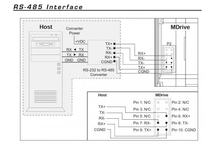
P2 is the RS485 interface (Gene5.jpg)

Look at this attached image. An X-Y positioner (Gene4.jpg) with two motors, both of which only have 3 wires exposed. Interesting.

Bob
 

Attachments

  • Gene4.jpg
    Gene4.jpg
    250.1 KB · Views: 2
  • Gene3.jpg
    Gene3.jpg
    453.7 KB · Views: 1
  • Gene5.JPG
    Gene5.JPG
    62.7 KB · Views: 1
That's the one! (Gene3)
I can't figure out the 3 wires. On a stage like that I'd expect at least two I/O for limit stops and maybe a third for "home". Do you know anything about their history?

I think building or buying a programming cable is probably the way to go, although it would be nice if you could ascertain that they work before going to the trouble. Does the spindle lock up when power is applied, but rotate semi-freely when it's off?

GsT
I have 3 points to make and I will start with the first two.
1. Aside from the fun of this, there is a matter of practicality (which I usually ignore!) I can by a stepper that I can deal with for less than the price a cable. I can buy two steppers for the price an USB-RS484 cable.
2. You may be able to help me here: So I get it hooked up and communicating with the terminal software. What do I program it in???? What are the commands?? What is the syntax?

I'll report back after I test some of the other motors.
 
That's the one! (Gene3)
I can't figure out the 3 wires. On a stage like that I'd expect at least two I/O for limit stops and maybe a third for "home". Do you know anything about their history?

I think building or buying a programming cable is probably the way to go, although it would be nice if you could ascertain that they work before going to the trouble. Does the spindle lock up when power is applied, but rotate semi-freely when it's off?

GsT
3. One motor locks up under power, putting the yellow/white IO line to ground does nothing, putting the yellow/white IO line to positive makes the motor click but not move (Defective? or needs more voltage or amperage)
One motor free wheels under power, putting the yellow/white IO line to ground does nothing, putting the yellow/white IO line to positive makes the motor turn at 30 RPM. (working)
Two motors lock under power, putting the yellow/white IO line to ground does nothing, putting the yellow/white IO line to positive does nothing.
 
Back
Top