Doing so is probably nothing new but for me, I am just starting to use the method and found it to be quite accurate and efficient - getting all the dimensions in one go instead of locating the features of the parts one by one. In a couple of occasions, the errors made in measuring with calipers were quickly identified with the aid of photos.
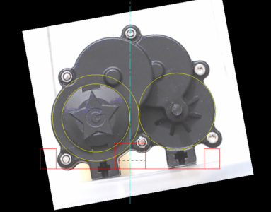
This is my recent work involving the use of photos. I have a gear box of an RC car that need be remounted to lower the center of gravity. To achieve that I need to make a new mount allowing the gear box to take up a tilted orientation. On top of that the gear box need be machined in order to mate with the new mount and a fixture need be made for the purpose. In doing so I need to locate some features on the gear box such as screw holes, the stands, the motors and so on. The way I did it was to take a picture of the gear box, import it into Nanocad ( essentially a free and old version of Autocad ), scale the image to 1:1 and rotate it to the desired angle before drawing the mount around the image and obtaining all required dimensions for machining.

There are two main sources of errors in this method :
1) Perspective distortion - this is an issue if the features to be located are not on the same plane perpendicular to the line joining the object and the camera. Perspective distortion causes the dimensions of features further away from the lens to appear smaller in the image. I am yet to figure out a simple way to eliminate this completely so I just alleviate the problem by using longer lenses ( e.g. 300 mm ) and increasing the camera-to-subject distance. May be a more rigorous correction method is to divide the image into several parts according to the distance from the camera and scale each part differently ? This can be done in photoshop manually but I am wondering if there are softwares that can do the same with less effort ?
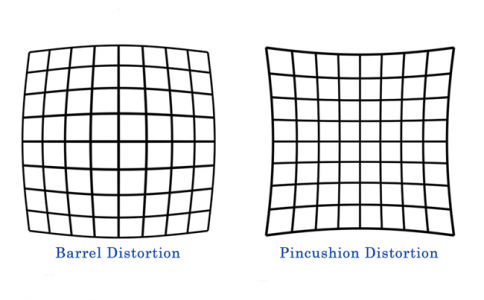
2) Lens distortion - this can be corrected in photoshop to some extent but I am yet to do it.

I will appreciate if those who have used this kind of methods can share some of your experience.
This is my recent work involving the use of photos. I have a gear box of an RC car that need be remounted to lower the center of gravity. To achieve that I need to make a new mount allowing the gear box to take up a tilted orientation. On top of that the gear box need be machined in order to mate with the new mount and a fixture need be made for the purpose. In doing so I need to locate some features on the gear box such as screw holes, the stands, the motors and so on. The way I did it was to take a picture of the gear box, import it into Nanocad ( essentially a free and old version of Autocad ), scale the image to 1:1 and rotate it to the desired angle before drawing the mount around the image and obtaining all required dimensions for machining.

There are two main sources of errors in this method :
1) Perspective distortion - this is an issue if the features to be located are not on the same plane perpendicular to the line joining the object and the camera. Perspective distortion causes the dimensions of features further away from the lens to appear smaller in the image. I am yet to figure out a simple way to eliminate this completely so I just alleviate the problem by using longer lenses ( e.g. 300 mm ) and increasing the camera-to-subject distance. May be a more rigorous correction method is to divide the image into several parts according to the distance from the camera and scale each part differently ? This can be done in photoshop manually but I am wondering if there are softwares that can do the same with less effort ?
2) Lens distortion - this can be corrected in photoshop to some extent but I am yet to do it.

I will appreciate if those who have used this kind of methods can share some of your experience.
Last edited:
