Gears and calculations

koenbro

H-M Supporter - Diamond Member
H-M Lifetime Diamond Member
Joined
Feb 23, 2016
Messages
480
I have 3D printed some gears in Fusion 360 using GF Gear Generator, with 50 and 25 teeth, Module 1.5mm, Pressure angle 14.5 deg, Helix angle 15 deg. The resulting large wheels are OD 78.5mm and small one is 40.6mm. How can I calculate spacing, meaning OC distance for them to mesh correctly? Is there a quick calculator? I have Machinery's Handbook open at "Gearing" and will slowly work my way through, but would happily take any advice to short cut the process.

By the way this is for an encoder attachment to a PM 728 mill that has a PDB.
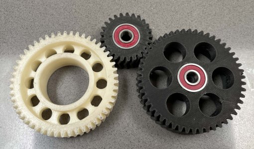
IMG_0351.jpg

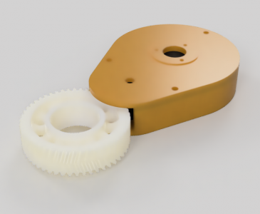
Version 1 looks like this. There is a top lid, the bearings are on the bottom side, and the Omron encoder connects from the top intot the farthest wheel.
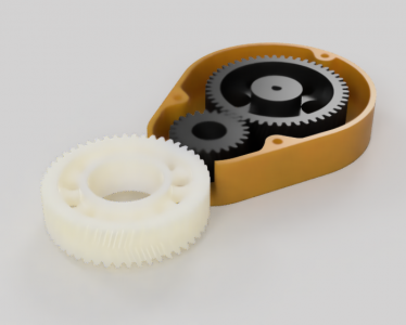
Omron_attachment_2022-Jul-17_07-45-59PM-000_CustomizedView13309052034.png

Omron_attachment_2022-Jul-17_07-49-09PM-000_CustomizedView24123212154.png
 
Last edited:
Persist with Machinery's Handbook, it's all in there and simple once you find the relevant tables.
 
 
A metric gear (Mod 1.5) with a 14-1/2 Deg PA sounds a lot like the 16 DP threading train on my Atlas. . .

The answer to your question lies in the theoretical "pitch diameter" of the gear. Think of two wheels running in contact, with a theoretical high coeffiency of friction. The OD of the wheels equates to the pitch diameter. Teeth are cut above (and below) this theoretical line to assure that the coeffiency is absolute, short of a broken tooth. The actual outside diameter will vary depending on the tooth configuration. But for every tooth design, there will be a formula where "pitch diameter" comes into play.

This then is calculated for each gear and the radius (1/2 diameter) of the two gears added together. This measurement becomes the center distance desired for running the two together. To determine the formulae for these, use Machinery's Handbook and search for "gear pitch diameter".

I apologize, my answer is a little convoluted. I am a night person and don't communicate well this time of day. There are many computer programs that will give a quick answer. My personal preference is to grasp the initial concept of a gear and do the calculations based on that understanding.

.
 
Using the definitions at the beginning of the Gears chapter in MH (Ed 29, pp 2025-9):

Module = pitch diameter (D) / number of teeth (N). The module is the inverse of the diametral pitch (P) which is used extensively. Although defined, MH does not appear to use Module much if at all, using instead P, the diametral pitch.
Thus D_big = 50 X 1.5 = 75 mm for the big wheel, and D_small is 37.5 for the 25 wheel.

The center distance C = (D_big + D_small ) / 2 = 56.25 mm

OD of a wheel is D + 2*a where a is the addendum.
a = 1 + P = 1 + 1/M = 1 + 0.66 = 1.66
OD_big = 75 + 3.33 = 78.33
OD_small = 40.83
 
Last edited:
As others have said you are looking for pitch diameter which is equivalent to two theoretical disks with the same ratio as the gears.

Clock makers use a thing called a depthing tool to fine tune or empirically find the best gear mesh. You probably don't need to go that far, but be aware that the best functional mesh will likely be a little different than your calculation.

In the past, I have setup one gear free running on a shaft mounted vertically on my mill table with the other gear free running on my spindle. It is then easy to adjust the spacing while evaluating the fit of the running gears, trading backlash for friction depending on your application.

Once you find the optimal spacing you then use that in your final assembly.
 
Pitch Diameter is the no. of teeth x the module of the gear for metric gears in mm for metric gears and the no. of teeth divided by the diamtral pittch in inches for inch gears. The center to center distance between two meshed gears is half the sum of the pitch diameter plus an allowance for clearance. The old rule of thumb for setting clearance was mesh the two gears witha piece of paper between them. This adds about .003" to each flank or about 009" for a 20º PA and .012" for a 14.5º PA to the center to center distance.
 
The center to center distance between two meshed gears is half the sum of the pitch diameter plus an allowance for clearance. The old rule of thumb for setting clearance was mesh the two gears witha piece of paper between them. This adds about .003" to each flank or about 009" for a 20º PA and .012" for a 14.5º PA to the center to center distance.

That’s a great rule of thumb. I placed the axes at the center distance plus 1mm. That is too much clearance and I get backlash but for this application lash is not an issue; if it gets too noisy I will reprint the housing with half mm or 20 thou clearance which will be closer to the rule.


Sent from my iPhone using Tapatalk Pro
 
Back
Top