G4000 ELS Upgrade

Cletus

Registered
Registered
Joined
Oct 24, 2013
Messages
485
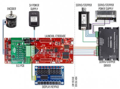
conversion.jpg
Back around 2005, I purchased my Grizzly G4000 Lathe and did quite a few very useful mechanical mods to it, leading to the publication with the help of others, two FREE handbooks "Tricking out the Asian 9 x 20 Lathe" and "Rebuilding The Asian 9 x 20 Lathe".
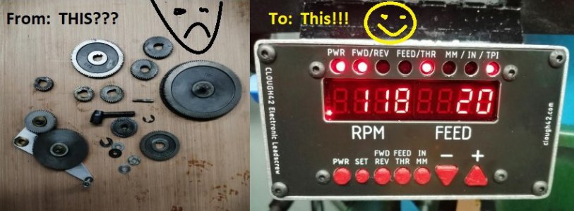
Well, this lathe has served me well and continues to do so. So it's time to do a little upgrade and I have chosen to implement the "Clough42 Electronic Leadscrew".
Here I I intend to log the developments of this build as Igo along. So, far, I have ordered the boards on ebay and also the Omron Encoder and Hybrid Servo Motor and Controller from Amazon.

Hoping this may be of help to someone going down this rabbit-hole, here we go:

Tricking-out the Asian 9X20 Lathe

Rebuilding the Asian 9x20 Lathe

 
Last edited:
What's done thus far:
1) Viewed the entire series of @clough42 videos relative to this mod.

2) Determined the G4000 has a different Spindle to Idler ratio (1:2) than James' lathe, so I'm going with 80T and 40T GT2 pulleys to couple the idler to the encoder.

3) Decided on a NEMA 24 Servo Motor / Driver combo and ordered it along with the Omron encoder.


4) Opting to build my own electronics enclosure from 16gauge CNC plasma-cut sheet.


Pulleys and Belts:


The 5mm Bore will have to be re-bored and reamed to 6mm for the encoder shaft.

This will need to be bored out to mount over the boss on the G4000's 80 tooth idler gear and will be secured to said gear by three 3mm SHCS bolts on the periphery (details to follow).


Power Supplies:

 
Last edited:
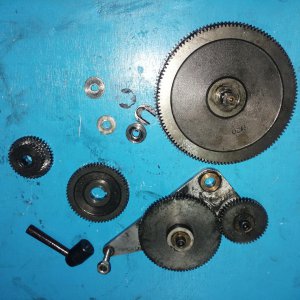
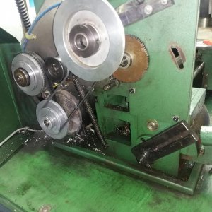
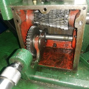
With all the stuff ordered from Amazon, ebay and DigiKey, today I ripped out all the change-gear and "reverse tumbler mod" stuff from the lathe to make room for the ELS mechanics (all modifications I do to my machinery is kept reversible as far as possible and this one is no exception).
I guess some housekeeping inside that gear-case is overdue?? :laughing:
Gears.jpgGearcase.jpg
 
Last edited:
I think this is evolving into a super-cool project!
While doing all this, two thoughts popped up:
1) The Quick-change Gearbox will now need to reside in the #1 position to maintain a 1:1 relationship between the intended input shaft on the left to the leadscrew or, I will need to mechanically couple the Servo-drive motor directly to the leadscrew at the right.

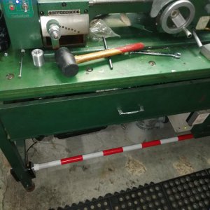
2) the second thought has nothing to do with the ELS really, but it would be nice to have a foot actuated spindle-brake of sorts. I think I can implement this quite simply by a footswitch (a bar across the base engaging a micro-switch) actuating a relay which de-couples the DC spindle motor from it's DC power supply and shunts the motor with a very high-power resistor (read water heater element), effectively using the motor's back EMF to accomplish some "electronic braking"
:fireman: :devil:
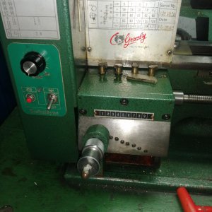
QCGB.jpgQCGB Internal.jpg
 
Last edited:
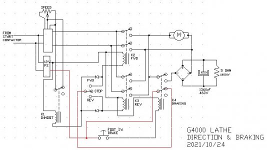
....and this is what I have on the drawing-board for the new direction and braking system after the ELS is implemented. The speed controller is already there (16 years), the direction switching is pretty straightforward and is a mod of the existing, and a mock-up of the foot-brake system proves successful. Essentially, for braking, we're removing power from the motor and shunting the motor with a massive, low value resistor, dumping the back EMF of the motor into this load (regenerative braking).

DirBrake.jpg


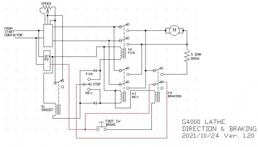
UPDATED DIAGRAM HERE:
DirBrakeV120.jpg

 
Last edited:
....and this is what I have on the drawing-board for the new direction and braking system after the ELS is implemented. The speed controller is already there (16 years), the direction switching is pretty straightforward and is a mod of the existing, and a mock-up of the foot-brake system proves successful. Essentially, for braking, we're removing power from the motor and shunting the motor with a massive RC network, dumping the back EMF of the motor into the load (regenerative braking).

View attachment 382994

It looks like you have a great start on the ELS.

Re: the brake, a coupl3e of points. It appears that you have a bridge rectifier to handle the fwd/rev situation so the capacitor always see the correct polarity. The capacitor will essentially be a dead short when the brake circuit is energized. As such the circuit can experience transient currents into the thousands of ohms which can destroy the bridge rectifier. You will also create a large amount of EMF which could interfere with the ELS. On a conversion of my lather to a dc PWM driven motor, I was destroying MOSFET transistors rated at 500 amps pulsed until I realized that I had to add a transient snubber to the motor. I have a 3,000 mfd filter in my power supply, directly connected to the bridge rectifier and I was destroying switch contacts until I added a inrush current limiter to the circuit.

But the question that I have is why bother with the capacitor and bridge at all? The capacitor will quickly discharge to zero volts after initial contact is made and really serve no useful purpose. The resistor alone will do the job. Transient current will be limited to a few tens of amps which will be easier on your relay contacts and reduce EMF.

As to the wattage of the resistor, the duty cycle of the brake will be minimal so a 1000 watts is overkill. You could do a calculation of the required wattage by assuming the the entire kinetic energy of the motor, spindle assembly, and work was being absorbed by the resistor and making a guess as to mass and its distribution and the maximum rpm. I did a rough calculation assuming 2,000 rpm and a mass of 20 kg located on a rim 4 cm in radius and calculated about 2,000 joules of energy. A 50 watt resistor can safely dissipate 3,000 joules/min so a start /stop every 40 seconds would be permitted. This should be a very conservative estimate.

I would venture to say that unless you were starting and stopping multiple times a minute, a 50 watt resistor with proper heat sinking would suffice. Of course, if you already have a water heater element and you have the room to install it, why not?
 
You are quite correct, thanks for the reply. I've been doing more testing this morning and ver 1.2 will lose the bridge and cap. As for the resistor, I have quite a few heater elements laying around and space behind the lathe stand is not an issue for it.
 
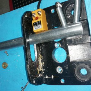
Well, the foot brake system is well on the way. Tomorrow I'll go and get me a bunch of relays.
Here's the trial fit:

Footbrake1.jpgFootbrake2.jpg
 
Last edited:
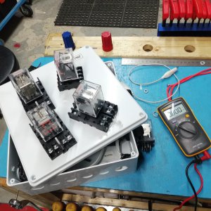
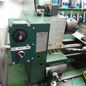
Making some progress. Got me a mess of DPDT 12V relays today and an enclosure suitable for repurposing. Also plasma-cut and fitted a new control panel, thus making ample room inside the lathe for the ELS stuff (I think). Another enclosure (metal) will house the ELS electronics. This will take care of the FWD - STOP - REV and the Foot-Brake part of it. Will deal with the left-over holes and neaten-up after it's all done. Paint is the closest match I could find at the hardware store, I did not really try too hard :)
I use this lathe a lot, so all the way through, I've got to keep it functional as I do the mods.

relays.jpg panel.jpg
 
Last edited:
Back
Top