With help from many of you, I was able to complete the conversion of my G0704 mill. Thank you.
See http://www.hobby-machinist.com/posts/503343/ for more background.
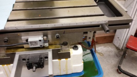
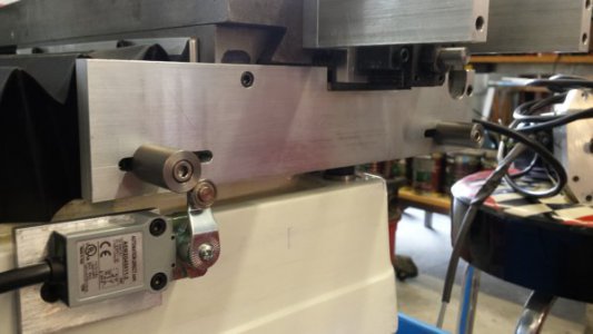
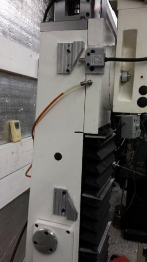
I have been able to make some small parts to mount my home switches for x, y and z axis and I am ready to mount the switches and set up Mach3. However, I am totally confused how to actually do it!
At present, I have two of three switches mounted, the Y and the Z. Both are attached with brackets to the machine column, the Z near the top and the Y near the bottom. The Z axis switch will be triggered when the head travels to the top extreme. The Y axis switch will be triggered when the table travels toward the column, just before it touches, but with enough room for the way cover to fold. This distance is approximately 0.75 inches. I have not yet decided where to mount the X-axis switch, either to the extreme left or extreme right of the table. All of the switch brackets have slotted holes to allow for approx. 0.5 inches of adjustment.
Questions:
Is there a convention for homing switch location? If not is there a preferred location?
Is there a convention for positive and negative direction for X, Y, and Z travel?
I'm using a C10 BOB and have 5 input pins, 10, 11, 12, 13, 15 available. I'm not sure how to connect the switches. The switches have Normally Closed contacts, which open when tripped. Do I need to use 3 of the 5 inputs, or can I connect all three switches in series and only require one input.
After connecting the switches, how do I make the necessary changes in Mach3?
What about soft limits? Are these set after the home switches are set up?
Finally, I'm not sure how to connect my emergency stop switch.
I realize there are many articles and You Tube videos describing all of this, but I have seen lots of contradictions and the more I read or watch the more confused I get.
Any and all recommendations will be sincerely appreciated,
Best regards, Frank


