Fusion 360 G-code bugs(?)

hman

Active User
H-M Lifetime Diamond Member
Joined
Feb 17, 2013
Messages
4,417
I recently bought a vintage DynaMyte DM2400 mill, converted to Centroid CNC, as a way of "taking the plunge" into CNC. I also bought Fusion 360, because my previous CAD software (CREO Elements Direct, free/restricted version) couldn't output any appropriate format. I've finally learned enough Fusion to design a CNC-ble part and used the Manufacture tab to produce tool paths. But I've run into some extremely irritating bugs, and wonder if anybody else has seen these and knows how to address them:

1. The G-code that Fusion outputs includes several instructions that have a colon ( : ) in them. Centroid does not recognize the colon as a valid character, and pukes out an error message. I've tried to search G-code reference info, but can't find any definition of the colon character.
2. For radial moves (G17), Fusion designates the radius with a P instead of the R specified by G-code. Again, Centroid pukes, and I have to go back in and do a universal find-and-replace to fix the code.
3. The alternate way to designate G17/18/19 moves is by using I and J. Unfortunately, Fusion uses absolute position values, while Centroid (as set up when I bought the mill) is set up to use relative I and J values. VERY interesting results! The tool paths I get when graphing with Centroid have lots of HUGE loop-de-loops. I think I know how to set the correct bit in Centroid to change to absolute I,J. But I was wondering if there's a way to tell Fusion to use relative values.
4. Following every tool change, Fusion output includes an H0 (ignore tooling height offsets), rather than the H1, H2, etc. that (I think) it should be using.

Thanks for any help!
 
Last edited:
1. The G-code that Fusion outputs includes several instructions that have a colon :)) in them. Centroid does not recognize the colon as a valid character, and pukes out an error message. I've tried to search G-code reference info, but can't find any definition of the colon character.

The colon is an end of line character, used in some G code flavors, machine specific. What post processor are you using?


2. For radial moves (G17), Fusion designates the radius with a P instead of the R specified by G-code. Again, Centroid pukes, and I have to go back in and do a universal find-and-replace to fix the code.

again what post processor?

3. The alternate way to designate G17/18/19 moves is by using I and J. Unfortunately, Fusion uses absolute position values, while Centroid (as set up when I bought the mill) is set up to use relative I and J values. VERY interesting results! The tool paths I get when graphing with Centroid have lots of HUGE loop-de-loops. I think I know how to set the correct bit in Centroid to change to absolute I,J. But I was wondering if there's a way to tell Fusion to use relative values.

You can set up absolute or incremental IJK values in Fusion, maybe in the post setup or you may have to edit the post processor.

4. Following every tool change, Fusion output includes an H0 (ignore tooling height offsets), rather than the H1, H2, etc. that (I think) it should be using.

This is set in the tool library.
 
Write your own code I did it professionally (as a tool & die maker) for almost 10 years. With NO training.
 
Gaw-lee, fellers ... who'd 'a thunk I needed one o' them post processor things? Ain't never heard of 'em, and din't ever git one afore.

Yes, my ignorance (and newness) is about as big as Jupiter!

Given your very useful advice, I searched for and found a Centroid post processor on one of Fusion's pages, loaded it successfully, and re-ran the post. Just one minor glitch - the first line of code (giving the program name) started with an "O", which errored out. Commented out that line, and was able to plot the tool paths. Did an "air" cut, looked OK. Made a test piece out of soft plastic (deck board). Now all I have to do is adjust the feed rates, so it doesn't go jamming and crashing (or stalling a stepper) through aluminum.

Yeeeee-Haaaaa! It'll be the "first ever" part I've designed entirely on a (NEW) CAD system and fully CNC machined. Quite a learning experience, but overall not too bad. Many thanks to all!

PS to Tom - I do plan to pursue the code-it-yourself route, and have done so with a simple part or two. But I also want to become skilled at the whole CAD/CAM process.
 
with all due respect to the pro's who have earned their place by writing G-Code from scratch. Let me say that it is important to understand basic g-code to be able to troubleshoot when things go wrong. (like commenting out the first line in your example above). Personally I think that after some basic gcode understanding your time is better spent learning to make a CAM program dance for you. (like Fusion 360) As you gain experience with the CAM portion you will be able to do some incredibly complex things much quicker than by hand coding. If all you want to do is cut straight lines or simple arcs then by all means, hand code the file or use the command line interface. Just my personal optionion :)
 
Just for fun, here are some photos of the part I've been talking about - my FIRST EVER part that's gone through the full process - designed on Fusion and CNC milled on my DynaMyte Dm2400.

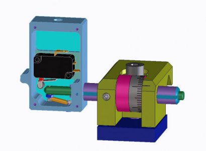
1. Design for a modification to my lathe carriage stop (originally posted at https://www.hobby-machinist.com/threads/carriage-stop.50189/ ). I want to include a microswitch that can be connected to the VFD and tell it when to stop the spindle (such as when threading to a shoulder). This design was done on my favorite CAD system, CREO Elements Direct. It's the CAD software I used when I worked at HP, so I know it well. But what I have now is the "hobbyist/free" version, which has various restrictions, including the fact it won't output any kind of format that any CAM software can use.
Stop n Switch 9520b.jpg

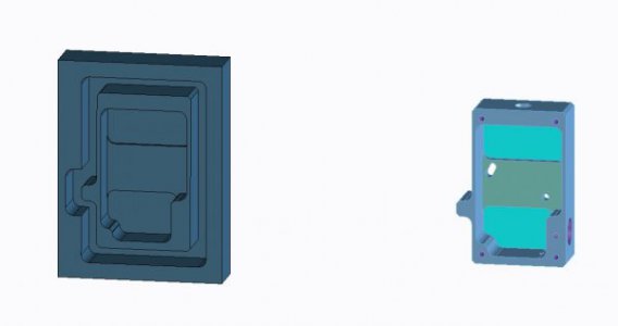
2. Copied the switch enclosure, added margins that allow the blank to be held in a mill vise. Holes omitted for simplicity.
Enclosure n CNC 9520b.jpg

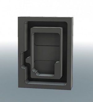
3. Same part duplicated in Fusion 360, which I'm just learning.
Enclosure Fusion 9520b.jpg

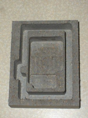
4. First test run on the DynaMyte Dm2400, using a piece of "Veranda" plastic/wood fiber decking for the stock - very easy to cut, and capable of maintaining relatively thin (.063") walls during deep cuts with a 3/16" end mill. Edges end up being pretty "fuzzy," so I cleaned most of them up with an Xacto knife before taking the photo.
kHPIM5930.jpg
 
Another PS to Tom -

Regarding hand coding G-code - yes, I recognize the value of knowing how, and have indeed done it to gain familiarity. Here's an example:

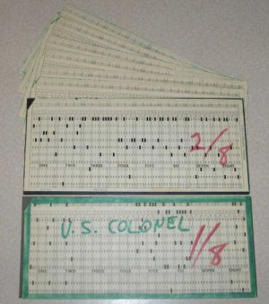
About a month ago I unearthed an old deck of IBM punch cards, circa 1970, containing the data for a graphic output by an IBM computer and Calcomp drum plotter. The program, requested by my CO, was "eye wash" for VIP visitors, meant to show off the various capabilities (including map overlays) of our intelligence data shop in sunny Saigon. It would plot out an unclassified certificate, commemorating the VIP's name, rank, date of visit, etc. Then it would plot out a representation of his rank insignia. I'd used graph paper to hand code a full set of these for all the US and VN officer ranks. The most complex, of course, was the colonel's eagle.

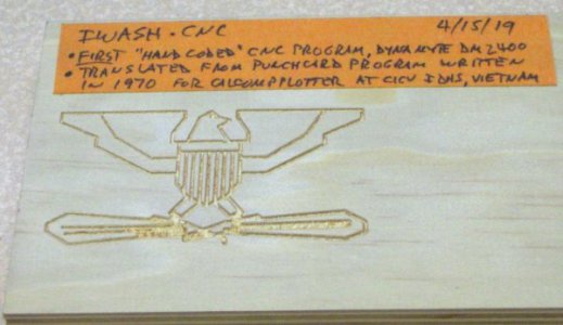
What I did recently was manually copy the numeric pen up/down and XY position data for the eagle into a spreadsheet. Then I translated the pen up/down commands into Z positions, added the "X" and "Y" characters, and used CSV output to create lines of G-code from the spreadsheet rows. Did a bit more massaging of the data and tried it out on my CNC mill, using an engraving cutter and a piece of plywood for a workpiece. The result of my first run is pictured below.

From this:
kHPIM5936.jpg

To this:
Iwash.jpg
 
Back
Top