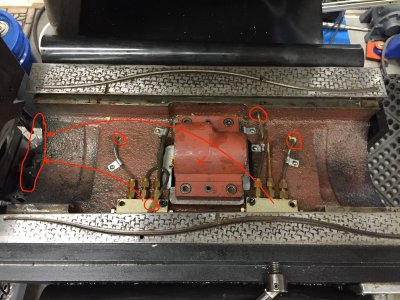
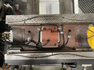
Got started on re-doing the oil distribution on my FTV-1. It's a circa 1978 machine, and has the old style pump that's built right into the right side of the saddle. I really like this feature, and intend to keep it, and run it till it fails. For now, the pump works great. However, the meters are plugged up, as are some of the lines and passages. While aesthetically pleasing, having the oil manifolds and all of the lines on the inside of the saddle under the table, make it a PITA to perform any maintenance and/or troubleshooting on the oil system.
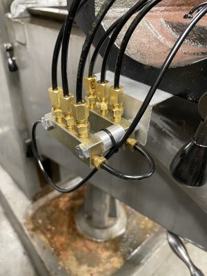
So, my plan is to relocate the manifolds over to the left end of the saddle, where the manifolds are normally located on "one shot" oil systems. Also, the four lines( circled in red ) that feed the X and Y ways are simply stuffed into holes in the castings that feed the passages that lube the ways. They're held in place with a blob of some sort of glue. For these lines, I intend to drill and tap for 90 degree compression fittings, and do away with the glue. The Y side of the nut, has the oil line going into a factory hole that I'll likely leave as is. It's facing down, and looks like there's little risk of it slipping out. The X side of the nut, is fed oil via a gooseneck of copper tube that simply hovers over the top of the screw, and dribbles oil on it. For this, I'll drill and tap the nut housing where the red X is, for another 90 degree compression fitting. This will line up with the saw kerf of the split nut inside, which will allow the oil to get all the way through to the screw inside.
Down the road, should the built in oil pump fail, I can simply bolt a Bijur pump to the side of the knee, and plumb it to the now openly accessible manifold, and be back in business. No more taking the machine apart for a basic maintenance task! Parts are on order, and hope to have them by this weekend. Meanwhile, if any of you see any "gotchas" I've overlooked, or have an alternative please chime in.


