First CNC'ed Part Made on My PM25 Mill

devils4ever

H-M Supporter - Gold Member
H-M Supporter Gold Member
Joined
May 13, 2019
Messages
1,016
Very exciting times. I finished my CNC conversion of my PM25 mill and made my first part. Since the CNC conversion kit I bought didn't have a cover for the column where the handwheel was located, I decided to make one. It's a simple project, but I learned a lot. I used FreeCAD for CAD/CAM and LinuxCNC on the mill PC.

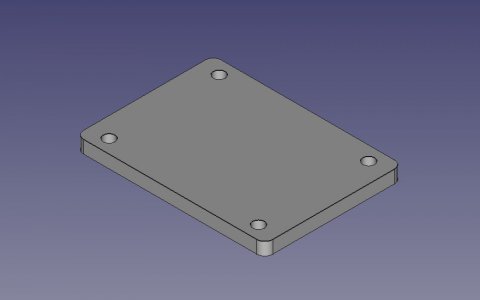
Heres' the 3D view of the part.
PM25MillZaxisSidePlateFiller.jpg

The biggest challenge was trying to determine how to hold this part since it's machined on all 4 sides. I came up with this for a solution.
1. Use a vise to hold the part and only do the drilling operation.
2. Clamp the part to the table with a 1-2-3 block underneath. Only clamp the 2 long sides in the middle. Set the Z distance so it clears everything. Use the quill to manually drop down to the part. As the tool nears the clamps, raise the quill. I single stepped the G-code for this.
3. After this is done, add clamps on the 2 short sides. Then, remove the clamps on the 2 long sides. This ensures the part doesn't move. Manually position the end mill and complete the uncut sections on the long sides.

Does anyone have suggestions on how to do this differently?

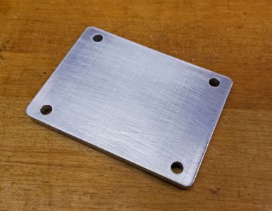
Take a look.
20200407_104210_edit1.jpg

It turned out better than expected. As for dimension accuracy, I got about 0.002" undersize on the short dimension and about 0.003" oversize on the long dimension.
 
Got it! That's a good idea. I got part of it right by drilling the holes first, then doing the profiling.

I'm just happy to see rounded corners! I know it's not much, but I could never do that manually on the mill. I've had to cut and file to do that.

Great thread you sent. I won't feel so bad when I break an end mill when someone as seasoned as you do it.

I still have to learn feed rates. I had the end mill taking 0.100" DOC at 5 IPM. For drilling, I had the feed rate set to 1 IPM. Both seem to work fine. I'm in no rush.
 
Congratulations, looks good.

Richard
 
Nice end mills are key for finding efficient feed/speeds. YG1 ALU-POWER is what I like to use.

Here is the 1/2" YG1 28593 end mill at work on a fairly stock PM25MV. I prefer the 3/8" 28584 but sometimes need the longer reach of the first end mill.

I have to conventional mill to avoid chatter (due to backlash), but you may not have to if you have decent ballscrews and nuts.


2500RPM .035 radial, .62 axial, .0069 IPT (51.7 IPM)
 
Luckily, I don't seem to have a chatter/backlash issue. Climb cutting is way smoother than conventional cutting.
 
I tried my second CNC project creating a round knob with circular cutouts. It ran great and looked really good. However, after measuring the lobes on the knob, I found that the knob is not exactly round. There are 6 lobes and measuring across the 3 pairs, I found two measured about 0.995" and the last one measured 0.988". That's a difference of 0.007". I'm assuming this is from backlash. Does this amount of backlash seem reasonable or excessive? I have double ball nuts for the purpose of reducing backlash. For this application, it doesn't hurt anything, but for other projects it could matter.
 
I tried my second CNC project creating a round knob with circular cutouts. It ran great and looked really good. However, after measuring the lobes on the knob, I found that the knob is not exactly round. There are 6 lobes and measuring across the 3 pairs, I found two measured about 0.995" and the last one measured 0.988". That's a difference of 0.007". I'm assuming this is from backlash. Does this amount of backlash seem reasonable or excessive? I have double ball nuts for the purpose of reducing backlash. For this application, it doesn't hurt anything, but for other projects it could matter.

Something is seriously wrong. As far as backlash, with double nuts I would expect 0 backlash and would not accept more than that. So first check the machine for backlash to see if that could be the problem.

Then cut a circle and see what you really have. Motor tuning could be in play here also. There are a number of things that can cause this, but check the mechanical first.
 
Although I personally ha e never done so,but I know that super glue or two sided tape is often used for hard to hold parts. Congrats on the new machine!
 
Something is seriously wrong. As far as backlash, with double nuts I would expect 0 backlash and would not accept more than that. So first check the machine for backlash to see if that could be the problem.

Then cut a circle and see what you really have. Motor tuning could be in play here also. There are a number of things that can cause this, but check the mechanical first.

I placed my Last Word indicator in on the spindle and jogged the X-axis back and forth by 0.010". The indicator moved about 0.009" showing about 0.001" of backlash.

Then, I tried the same for the Y-axis. It showed 0.005" of backlash. So, I think this is the cause. I tried tightening the mounting screws and the screws on the coupler, but it didn't seem to help. The Y-axis has a threaded end on the ball screw. So, I tried loosening the screw on the coupler and locking the table and advancing the table a few thousandths to see if that would tighten it. That didn't seem to have any affect. I'm assuming there's some play where those bearings are in the mount. Any other ideas?
 
Back
Top