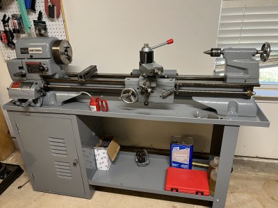
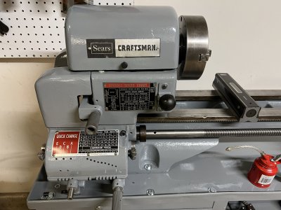
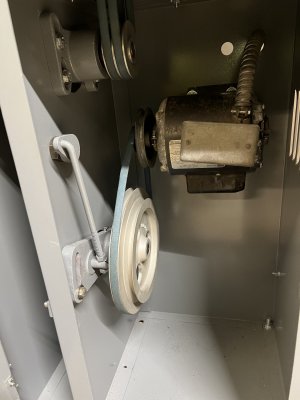
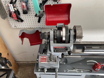
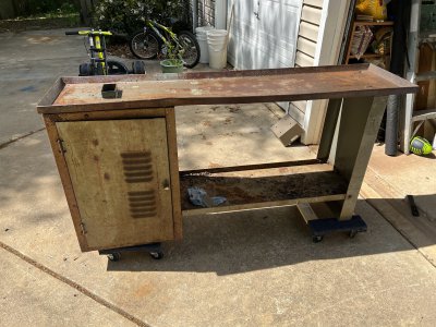
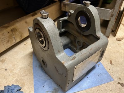
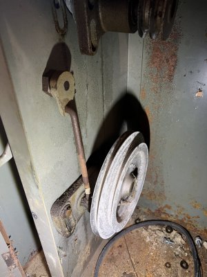
Oh Yum!! That is just beautiful!
Re: "Leveling". Yes indeed, read up on it as much as you can, until you fully understand why we use levels on lathes at all.
As I understand it, getting all the important way surfaces and other parts aligned is the mission, and using a level provides the handy, stable, reference to make it happen. A lathe does not, in theory
have to be "level" in its set up resting place, so long as all the surfaces are aligned correctly, and not being put out of shape by the lathe's own weight. Lathes on ships are aligned to the ship's construction reference line, instead of to the Earth gravity horizon. For us landlubbers, we might as well use horizon instead of some offset.
Your level lets you check out whether there is any twist in the bed. A very sensitive level, walked along the ways in equal advance increments can let you figure out whether there is a "bow" in the shape. This you do if you don't have a reference straight edge. You can check the ways individually, or put parallels across, and get a different perspective. (There might be end wear in only one way).
Using a dial gauge.
One can find videos showing way wear being "measured" using a dial guage mounted on the cross slide. Yes, you can get a lot of information from that, and indeed, if you get to the point you can move the carriage the length of the lathe, and the gauge reads constant, it has to be straight.
[Edit: or a piece of a very large, unlikely, sphere!

]
That said, keep in mind the cross slide itself fits against the ways against points unknown underneath, and provides a kind of "average" between the touching points as it moves. One can also get up to tricks if there is an available unworn reference surface along the length. My South Bend, with prismatic ways, has several of them, including the top edge of the ways . I don't know if the Atlas has any handy surfaces
Is the "bow"from wear? Is it just stressed as it rests?
You can go a long way to checking whether it might be wear, or not, by first looking hard at the ways, and trying to estimate any wear ridge. Note that your Atlas sets down on what looks like four bolt-down points below the cantilever extended mount feet. I don't know how these are attached to the lathe bed. Now consider that the lathe bed can rest stable on only three points. The fourth is kinematic redundant, and if simply tightened up hard, will pull a twist, or a bow into the structure. I temporarily supported my lathe between the front two headstock bolts, and some shim under the foot at the tailstock end. Checking only for twist, I made sure that bolting on the tail foot did not cause twist. Then I removed the shim, and again looked for the twist effect. My mount bolts have a extra nut and washer under to allow adjust, and the top nut is just to lock up tight.
One or other of the supports will be taking most of the strain, but here you do the obvious. You level along the axis by adjusting both at the tail end, starting with the headstock end level across. Then level the tail end across, differentially, one at a time. I had to keep checking the headstock end, and the axial level between adjusts, and I thought it OK to temporarily allow axial level to offset a little, so long as it was in both ways together. In practice, they did move together
It can drive one mad going around in circles. What worked for me was trying to fix twist by adjusting one side to about half what was needed, then moving to the other side, and adjusting the "other" direction, kind of "sharing" the twist. When came time to adjust axial level, I put feeler gauge shim under the end of the level, and "extrapolated" by the proportion of lathe to the length of the level. From the pitch of the bolt threads, you can figure how much of a whole turn provides the adjust amount. Both sides at the tail end get that, with a passing check that twist is still OK.
After you are sure it is level both ways..
You want to know if it is bowed, or maybe worn at the ends. You need also be reasonably sure the tailstock axis is pointing parallel to the ways. You can use a test bar, or make a dumbell test bar. Use a micrometer, and do all that good stuff amply described here. Starting with no other aids, you can resort to Rollie's Dad's Method, though I found it easier to just get a "made in India" test bar. At this stage, if a dial gauge mounted on the carriage shows variation along the top of a reference test bar, that would be a sign that the carriage is moving up and down on wear.
Expensively, you can also check with a straight edge. Without that, but with what you can hang together to make a measure tool for using your level, you can try for a
Kingway-type alignment tool. They can get very fancy, or they can be some stuck-together lash-up. No matter, they both work just as well. I did not have to go so far as using one, so I do not have direct experience of tangling with this stuff, but I may make one in the future.
The fancy one
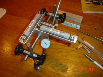 The "Ghetto" version
Rex Walters used a piece of scrap metal with two washers super-glued to provide a couple of touching points to an unworn surface (right side of picture), and clamped it to his level, then he measured with a dial gauge to a gauge block against the way (left side of pic).
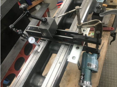
I know this stuff is to be had somewhere deep within HM, but for convenience, I reiterate here. Please forgive if I be saying stuff you already know. Maybe other readers might like to try this stuff. I was not altogether successful at the beginning. One can mess up quite a lot, and be driven to give up unless one has some nice, understandable recipes to follow. Here I have posted some suggested dimensions for the measure jig, and other info.
Of course, you may not need to get up to all this, but I do think you need to know for sure why a level on your lathe bed droops at the ends. Your lathe is such a excellent restoration, maybe the best I've seen. I think it deserves that you play with it with an eye to what it finally needs

