Enco 110-1351 control panel wiring diagram

biednick

Registered
Registered
Joined
Feb 8, 2024
Messages
17
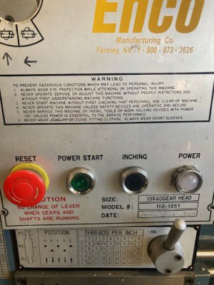
I'm looking for a wiring diagram or picture of a properly wired control panel for an Enco 110-1351. I picked one up for my home shop, and the emergency stop button was broken and wired around. I replaced it and the burnt out power bulb. Everything functions as expected except the power bulb, which is on any time the lathe is plugged in regardless of the state of the e stop and power button.

I found a wiring diagram for a G4003 (which is the lathe I used previously) on manualslib. I can use that as a starting point and trace all the wires to verify it's correct if I need to, but I'd prefer to avoid that if possible.
 
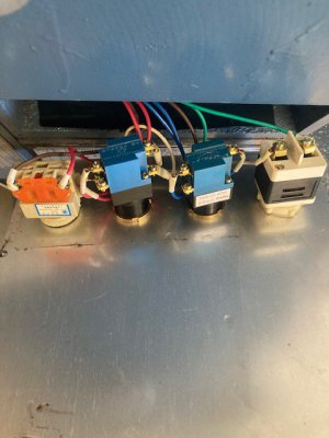
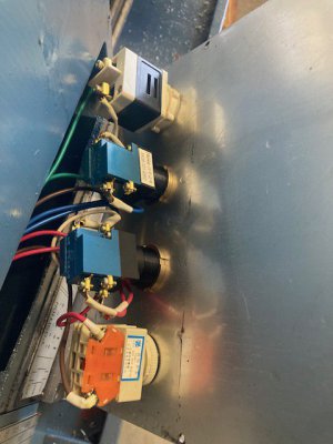
Here are a few pictures of the control panel of my 110-1351 and the manuals. The light is on all the time on mine as well so maybe you've got it correct.
IMG_3662.jpgIMG_3661.jpgIMG_3663.jpg
 

Attachments

  • Enco - Lathe 110-1351007- Operation Manual.pdf
    1.9 MB · Views: 150
  • Enco-Lathe 110-1351 Parts List.pdf
    593.5 KB · Views: 157
Yep the light should be on when there is power to the lathe.
 
Here are a few pictures of the control panel of my 110-1351 and the manuals. The light is on all the time on mine as well so maybe you've got it correct.
View attachment 477892View attachment 477893View attachment 477896
Thank you, I'll check it out tonight and compare your pictures to the wiring on mine. I just assumed it'd be off when the e stop is pressed like other import lathes I've used.

I appreciate the manuals too. I found a generic manual for import 13x40 and 14x40 lathes from the early 2000s that's usable, but yours look much more complete.
 
Yep the power light is run directly from the transformer, so when the lathe has power it's on.
Radials: Thanks for posting that manual, some valuable electrical info there I didn't have including a pictorial wiring diagram
Also some mechanical specs and gear info I have never seen before.
You definitely should plan on submitting that for upload to our database
The pictorial has some hand-drawn notes that may be erroneous, I just noticed
 
Last edited:
Yep the power light is run directly from the transformer, so when the lathe has power it's on.
Radials: Thanks for posting that manual, some valuable electrical info there I didn't have including a pictorial wiring diagram
Also some mechanical specs and gear info I have never seen before.
You definitely should plan on submitting that for upload to our database
The pictorial has some hand-drawn notes that may be erroneous, I just noticed
I had found those manuals as pdfs online when I was looking to buy the Enco lathe I have. My lathe did come with the original manuals that are an exact match to these ones. I can't speak to the notes written on the pdf version as they're not mine. Perhaps I'll do a clean scan of my manuals an upload them.
 
I checked it out last night. It's wired properly, it's just not designed to work how I expected and would like it to. My new e stop has an extra switch so I just ran one leg for the light through it, and it works the way I want it to. Thanks for all the help.
 
Hi @biednick

Glad you got things figured out.

Yes, many of the E-stops are simply wired in series with the power. Power to the lathe usually means the light is on when the switch is lighted when the power is flowing. However, as you have found you can get around this or connect things in multiple ways.

Also, I have found that many of the lathes use very similar wiring to control a 3 phase motor and only minor changes to control a single phase motor. I have PM1440GT with a three phase motor. However, I converted it to run from single phase power via a VFD. During this process I studied the original electronics and decided I should write up how the electronics works, especially the safety aspects, just in case I ever wanted to put it back! So I prepare a description of the original electronics with my version of the circuit drawings. You are welcome this info if you like. I posted this information at the following:
VFD conversion using solid state electronic components.

The original electronics are described as the first attachment, called "PM1440GT Part 1 FacOriglElec....." The circuit layout is the last figure in the document. Of course the words in the document explain how these work. You will see the E-stop is in series with the 24 volt power that controls the relays (contactors) and so any E-stop light could only have power when the E-stop switch is conducting, unless there is internal switching. In my lathe's circuits there E-stop was unlighted, but a separate light bulb is attached after the E-stop switch goes directly to ground. Hence, if the E-stop is tripped (open circuit) then light goes off.

The posting maybe useful as it has now been downloaded 319 times... More often than the VFD conversion document!

The rest of this contribution includes a description of my VFD conversion and shows lots of these details. Part 2 describes the conversion.

Dave L.
 
Hi @biednick
I took a quick look at your manual and parts document. You have a nice gear box with 8 fundamental TPI plus 5 doubles you can make without changing the external gears. I also have a SB lathe with this style Norton gear box. I love it. However, this does not tell you much about what you get if you change the external gears around. Sometimes there is a thread you want to make which is a bit non-typical.

If you want a spread sheet that will generate all of the possible TPI values with gears in other positions I posted one that I made up. It is designed with multiple sheets so that one can added new lathes and get results for your individual lathe. It also comes with macros which will generate tables of TPI values and provides sorting and searching capabilities. You will find the last version that I posted here.

Nov. 6 2023 Excel workbook file name: TPI_ManyLathesRev1 NB06_0054.xlsm

However, I am in the process of writing a new version which handles merging of duplication of exchange gear arrangements better (not important for you). One of these days I will post it.

Dave L.
 
Hi @biednick
I took a quick look at your manual and parts document. You have a nice gear box with 8 fundamental TPI plus 5 doubles you can make without changing the external gears. I also have a SB lathe with this style Norton gear box. I love it. However, this does not tell you much about what you get if you change the external gears around. Sometimes there is a thread you want to make which is a bit non-typical.

If you want a spread sheet that will generate all of the possible TPI values with gears in other positions I posted one that I made up. It is designed with multiple sheets so that one can added new lathes and get results for your individual lathe. It also comes with macros which will generate tables of TPI values and provides sorting and searching capabilities. You will find the last version that I posted here.


However, I am in the process of writing a new version which handles merging of duplication of exchange gear arrangements better (not important for you). One of these days I will post it.

Dave L.
The gearbox was a must have for me. I don't want to deal with change gears every time I want to change feed or thread pitch.

I appreciate the spreadsheet. I'll definitely save it for later. I only came across one thread I couldn't cut on the G4003 I had been using. I think it was .49-27. I was able to cut it with a 1/2-27 die but it would have been nice to have the option to single point thread it. An electronic lead screw is something else I've thought about, but that'd be way down the line.
 
Back
Top