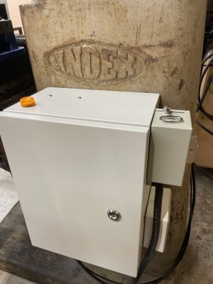
After too much research and studying the probably overbuilt electrical box for my Index 645 mill is installed and functioning. The heart of the electrical system is an Automation Direct GS21-21P0 which is a .75 Kw 240V single phase to 240V 3 phase VFD. Automation Direct recommended not oversizing the VFD. The primary motor on the mill is 1 hp/.75Kw. There may be some unnecessary components added but it does what I wanted and it's working well. There are plans to expand the function and move the controls o the head of the mill when time and energy permit.
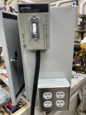
There was an existing outlet that powered my woodworking dust collector so I installed a way oversized box over that outlet's opening, ran conduit up a little way and then about 5 feet to the left to restore power to the dust collector. I chose to bring the 240V single phase power into the box through a 4 conductor cord to provide both a neutral and a ground. The power is switched via a 3 pole 30A Leviton switch housed on the outside of the box in a Leviton box designed for that switch. It's a very robust, commercial grade combination.
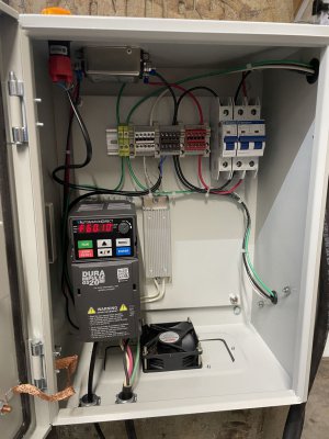
Inside the box the 240V lines go to a 20A 2 pole breaker that splits one leg off to a single pole 20A breaker for 120V access. The breakers and power distribution are mounted with a Dinkle DIN rail terminal block kit which made it very easy to keep the wiring reasonably organized. The Dinkle kit is from a company in Florida (via Amazon) that was a delight to work with. It included jumper bars that allowed multiple terminal blocks to conduct the same leg as well as ground blocks that are immediately identifiable because of their distinct color. The DIN rail is extruded anodized aluminum and much nicer than the stamped steel versions. I painted the front faces of the terminal blocks to correspond with the wire color of each leg. It's not the neatest wiring job ever but it's orderly and easy to trace a wire should it ever become necessary. There are also some end caps for the blocks that eliminate contact between the logs of the circuit. The 240V circuit goes through an RF noise filter and then on to the VFD.
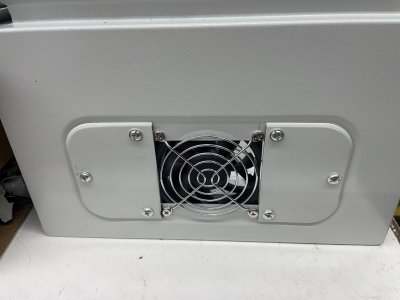
On the 120V side the pilot light and fan are wired directly to the DIN connectors and power is also sent to an externally mounted 2 gang 120V outlet box. A 120V pilot light is installed on top of the box so there's a visual notification that the box is powered up as I shut off the lights and close down the shop. A 120V computer fan was installed in the bottom of the box for some forced air cooling. The fan makes a little noise so it's another reminder that the power is on. Automation Direct indicated that forced air was not necessary for the VFD that I used but since I installed a braking resistor and will eventually add a second VFD for the X axis motor it just seemed like the right thing to do. Only the primary motor controls will be moved to the head. There's little need for the X axis to be variable speed since it had a broad range of speeds available through its transmission.
The mill's forward/stop/reverse is connected to the original Hubbell switch and configured in the VFD to work with the external control. I like that much better than having to use the tiny membrane switches on the VFD's control panel.
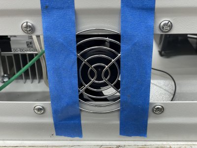
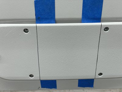
To mount the fan I first drilled the mounting holes and then marked the edges of the fan with blue tape. The edges were transferred to the cover plate and marked with a Sharpie so I knew where to cut.
Future additions will include a digital tachometer which will need 120V power, the aforementioned second VFD for the X axis motor which is also 3 phase and a DRO.
There was an existing outlet that powered my woodworking dust collector so I installed a way oversized box over that outlet's opening, ran conduit up a little way and then about 5 feet to the left to restore power to the dust collector. I chose to bring the 240V single phase power into the box through a 4 conductor cord to provide both a neutral and a ground. The power is switched via a 3 pole 30A Leviton switch housed on the outside of the box in a Leviton box designed for that switch. It's a very robust, commercial grade combination.
Inside the box the 240V lines go to a 20A 2 pole breaker that splits one leg off to a single pole 20A breaker for 120V access. The breakers and power distribution are mounted with a Dinkle DIN rail terminal block kit which made it very easy to keep the wiring reasonably organized. The Dinkle kit is from a company in Florida (via Amazon) that was a delight to work with. It included jumper bars that allowed multiple terminal blocks to conduct the same leg as well as ground blocks that are immediately identifiable because of their distinct color. The DIN rail is extruded anodized aluminum and much nicer than the stamped steel versions. I painted the front faces of the terminal blocks to correspond with the wire color of each leg. It's not the neatest wiring job ever but it's orderly and easy to trace a wire should it ever become necessary. There are also some end caps for the blocks that eliminate contact between the logs of the circuit. The 240V circuit goes through an RF noise filter and then on to the VFD.
On the 120V side the pilot light and fan are wired directly to the DIN connectors and power is also sent to an externally mounted 2 gang 120V outlet box. A 120V pilot light is installed on top of the box so there's a visual notification that the box is powered up as I shut off the lights and close down the shop. A 120V computer fan was installed in the bottom of the box for some forced air cooling. The fan makes a little noise so it's another reminder that the power is on. Automation Direct indicated that forced air was not necessary for the VFD that I used but since I installed a braking resistor and will eventually add a second VFD for the X axis motor it just seemed like the right thing to do. Only the primary motor controls will be moved to the head. There's little need for the X axis to be variable speed since it had a broad range of speeds available through its transmission.
The mill's forward/stop/reverse is connected to the original Hubbell switch and configured in the VFD to work with the external control. I like that much better than having to use the tiny membrane switches on the VFD's control panel.
To mount the fan I first drilled the mounting holes and then marked the edges of the fan with blue tape. The edges were transferred to the cover plate and marked with a Sharpie so I knew where to cut.


Future additions will include a digital tachometer which will need 120V power, the aforementioned second VFD for the X axis motor which is also 3 phase and a DRO.

