- Joined
- May 25, 2016
- Messages
- 181
I'm working on the DRO for my Enco branded mill drill. Yep, there's a dozen posts out there for people doing the same, but the pictures are not always that great, and many chose the magnetic scales, not glass, so I wanted to get some pics out there and ask some questions.
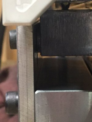
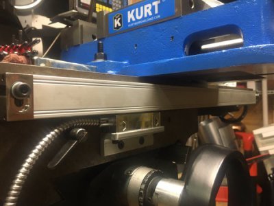
X-axis is about as straightforward as you can get - I re-used the dovetail nuts that held the table stops. Drilled 2 holes (M5 - don't ask - the rest of the mill is all Metric, so I figured I'd keep it all metric) for a thick piece of angle that I turned into a mounting bracket for the read head. Done, works.
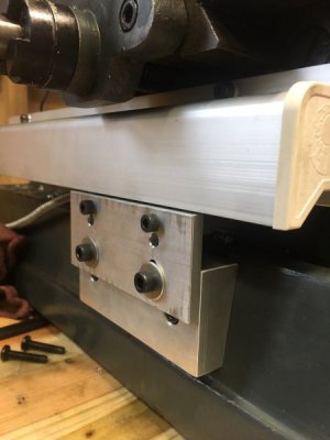
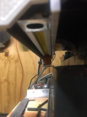
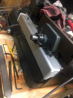
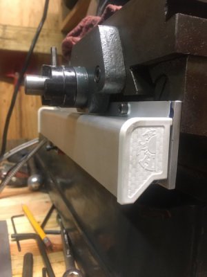
Y-axis - I found two flat spots on the carriage, so I drilled and tapped (again M5) and hung a piece of 3/16" aluminum bar, which I previously marked and drilled for the scale to mount, as well as some M5 (or M4, I forget) for the chip guard. That bolted on, and seems solid.
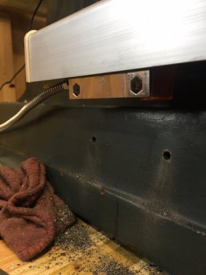
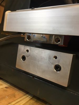
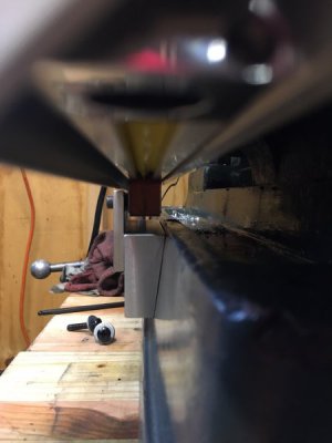
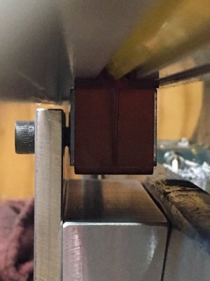
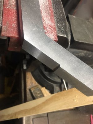
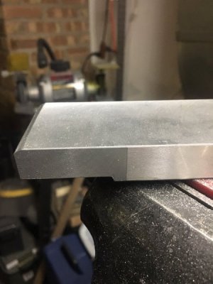
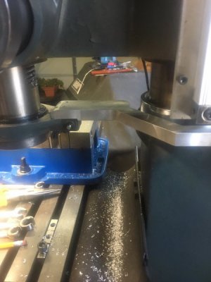
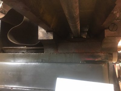
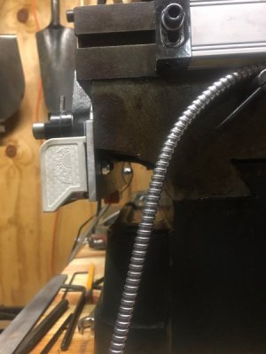
Now the fun part - mounting the read head somewhere. As you can see from the first pic below, I mocked up a piece of angle, just to see how things might fit. I'm thinking about milling a block of aluminum (I have plenty of 6061 cutoffs to work with) at a 5 degree angle to mate with the casting. Then use a piece of angle to give the read head some adjustment capability. Any issues with my plan? How crucial is it that the read head be perfectly horizontal when mounted? I can probably get it within 0.5 degrees with no issues. (casting irregularities may be fun).
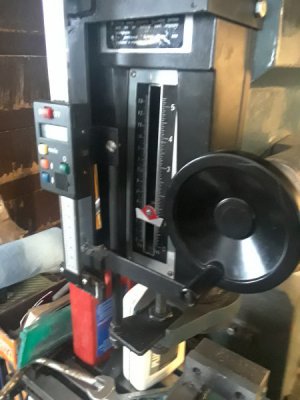
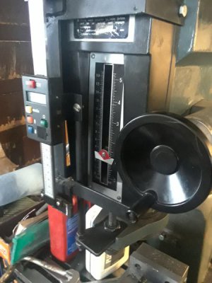
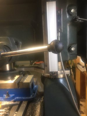
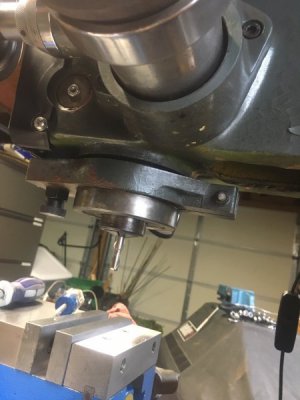
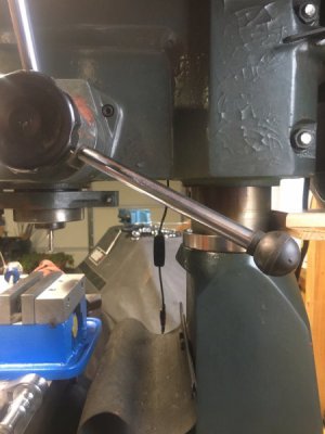
Lastly the Z-axis. There is a ring that clamps around the spindle. Seems I can take that off, drill and tap for some sort of aluminum plate/bracket, and extend it back or off to the side. I don't want to risk bumping the scale or read head when I raise/lower the head, so I'm undecided which side it should go on. I lean toward the LEFT side. Any ideas appreciated here.
The Kurt vise looks a bit out of place, right? I refurbished it, it's not new. (couldn't justify a new one...)
Thanks in advance!
-Tom


X-axis is about as straightforward as you can get - I re-used the dovetail nuts that held the table stops. Drilled 2 holes (M5 - don't ask - the rest of the mill is all Metric, so I figured I'd keep it all metric) for a thick piece of angle that I turned into a mounting bracket for the read head. Done, works.
Y-axis - I found two flat spots on the carriage, so I drilled and tapped (again M5) and hung a piece of 3/16" aluminum bar, which I previously marked and drilled for the scale to mount, as well as some M5 (or M4, I forget) for the chip guard. That bolted on, and seems solid.
Now the fun part - mounting the read head somewhere. As you can see from the first pic below, I mocked up a piece of angle, just to see how things might fit. I'm thinking about milling a block of aluminum (I have plenty of 6061 cutoffs to work with) at a 5 degree angle to mate with the casting. Then use a piece of angle to give the read head some adjustment capability. Any issues with my plan? How crucial is it that the read head be perfectly horizontal when mounted? I can probably get it within 0.5 degrees with no issues. (casting irregularities may be fun).
Lastly the Z-axis. There is a ring that clamps around the spindle. Seems I can take that off, drill and tap for some sort of aluminum plate/bracket, and extend it back or off to the side. I don't want to risk bumping the scale or read head when I raise/lower the head, so I'm undecided which side it should go on. I lean toward the LEFT side. Any ideas appreciated here.
The Kurt vise looks a bit out of place, right?
Thanks in advance!
-Tom


