Drawing a metal rack in Fusion 360

Just for fun

Tim Young
H-M Lifetime Diamond Member
Joined
Oct 7, 2020
Messages
2,347
I was playing around in Fusion 360 tonight trying to draw an outdoor metal rack for a bunch of used metal that I have just stacked on the ground behind the shop.

I have somewhat of the basic design down. But now I want to change some things and add others. To start with I made it 16' long 2-point rectangle with the origin in the mid-point of one of the long sides. I would like to change it to 12' but the problem is sense I centered the drawing mid-point the program decreases the size at least from the base from both sides. I also wanted to put a shelf of the front edge if you will at 12" wide. I have a total of eight sketches.

What I have drawn right now is 16' long 3' wide by 5' tall with 5 uprights and 5 cross pieces that are 2' wide. The cross pieces are actually 3' wide, but one foot extends 1' past the upright for a mesh shelf of some sort for small items.

So, I realize it's probably just about impossible to tell someone in a forum like this how to draw in Fusion 360. But how or what is the right way to draw something like this. I'm thinking it is considered a 2D drawing, but when I search 2D drawing all I can find is make a 2D drawing from a design.

I have included a screen shot to get an idea of what I was trying to do. I don't know how or even if I can share the drawing I am working on.

Tim
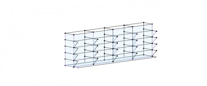
Metal Rack v5.jpg
 
Fusion360 is modeling software that produces 2D drawings of your components for manufacture, I’m not aware of a way to make a 2D drawing without making the 3D model first.

For what you are doing, each part needs to be a separate component in the model space, otherwise when you create a drawing, everything will be shown and it will be very difficult to dimension. A component in this sense is a part of the assembly you will be making. In your example, you would make the 16 ft poles as a component, the vertical poles as another, etc. Each one of those pieces would be a separate component that you can make a drawing from, but you can also resize and reposition as needed. You can also easily copy components to make any number of additional components and place them where needed once you made the first one so you are not drawing each part multiple times. There is a way to copy the component so it is a separate component, or that a change in one changes all of them, but can’t remember how right now.
 
I agree with the above but you don’t strictly have to use separate components. If you model parts as separate bodies in a component you could selectively include them in a drawing. Also, even drawing the overall rack as a single body may work if you want a drawing of overall dimensions.

The solid-modeling distinction means that instead of lines representing the rack members, you want to draw a section/projection and extrude it to make a solid part. Like draw a 1” square then extrude that’s to make a 1” bar. Sometimes you’ll want to model the full detail of a hollow tube (wall thickness) but other times that may not be necessary.
 
Thanks for responding. Once I had the layout down, which I never could complete. I was going to use the pipe command to make it a 3D. It's not that I really need to do this just trying to learn how to do different things.

I'll try using different components and see where that leads me. I was thinking along those lines using different scathes, it didn't work.

jwmelvin, Your thinking separate bodies might be better. I'll check it out.

Thanks again
 
Okay, using the pipe command may make sense.

The issue you were having seems to relate to constraints used in your initial sketch. If you use the center-rectangle function, f360 will impose certain constraints on a rectangle and construction lines to make that happen. It’s often useful to draw with the sketch primitives (e.g., an unconstrained rectangle), then apply the constraints yourself.

One thing I don’t like about f360 is how it shows constraints. I’d like to get a more deterministic list of constraints in a sketch or associated with a particular sketch element.
 
As an old drafting table / AutoCad guy it took me a long time to get my head around Fusion 360. I just couldn't understand that it is 3D modeling software and not 2D drafting software. I was trying to make it work like AutoCad and that just wasn't happening, even to the point of creating dxf's in AutoCad and importing them into Fusion. Once the light bulb came on Fusion became a pleasure to work with. Now it's easy for me to create machine designs and complex assemblies out of individual components.

For the most part I draw individual pieces and assemble them in an assembly model, separate from the component models. Example, if I need a 2'' square tube 3 ft long, I open a new model, create a sketch of the tube cross section, extrude to 36 inches and save. Then go back to the assembly model and Insert to Current Design to bring the new square tube into the assembly model. Then place it using the Joint or Align tools. Overall it works just like you were actually building the structure with real materials and a welder.

There are a couple of ways to share models. 1) you can share with anyone that has a Fusion account, and 2) you can right click on the model in the Project Explorer pane on the left and select Share Public Link. This allows anyone to view your design in a web browser.
 
I agree with the above but you don’t strictly have to use separate components. If you model parts as separate bodies in a component you could selectively include them in a drawing. Also, even drawing the overall rack as a single body may work if you want a drawing of overall dimensions.

The solid-modeling distinction means that instead of lines representing the rack members, you want to draw a section/projection and extrude it to make a solid part. Like draw a 1” square then extrude that’s to make a 1” bar. Sometimes you’ll want to model the full detail of a hollow tube (wall thickness) but other times that may not be necessary.
Thanks for the correction, I didn’t realize you could do that with bodies, I’ll have to give that a try.
 
JimDawson, That's a good idea, I did something like that designing my control boxes for my mill. The problem is I only have the hobby version and only have 10 drawings I can save to work with. I'll try the Share Public Link thing again; it didn't work the first time I tried it. Something about I didn't have anything to share. Maybe because I hadn't extruded any of the components yet. I'm going to re-draw it before sharing.

Thanks guys!

Anyway, I need to run so it will have to be later.

Tim
 
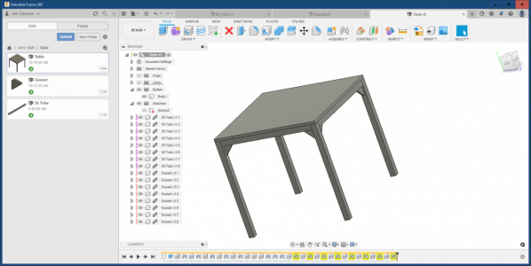
Here is a quick example. This assembly consists of only 3 pieces, the Table Top, 2'' square tube x 36'', and the gusset. Took me about 15 minutes to draw and assemble. Here is the public share link https://a360.co/3MkTwYP This opens in any browser.

1646245410124.png
 
JimDawson, That's a good idea, I did something like that designing my control boxes for my mill. The problem is I only have the hobby version and only have 10 drawings I can save to work with. I'll try the Share Public Link thing again; it didn't work the first time I tried it. Something about I didn't have anything to share. Maybe because I hadn't extruded any of the components yet. I'm going to re-draw it before sharing.

Thanks guys!

Anyway, I need to run so it will have to be later.

Tim
You can save as many files as you want, you can only have 10 active at a time with the hobby account. The includes drawings of your model as well. If you reach the limit, just deactivate the ones you are not using and then you can start or save a new file.
 
Back
Top