- Joined
- Nov 23, 2014
- Messages
- 2,634
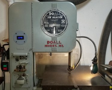
This will take a couple of posts because as usual I'll go into nauseating detail. . . Back story is I bought a circa 1948 DoAll ML band saw between Christmas and New Years last year. Being 70+ years old, there were a few things that needed some repairs. DoAll saws are known for their rotating Job Selector wheel which gives recommendations for filing, blade speeds, blade width and blade teeth per inch depending on the material/thickness being cut. For speeds, the important factor is “feet per minute”.
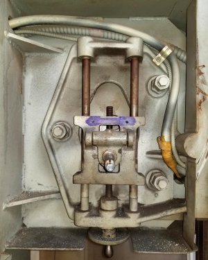
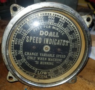
My saw came with the standard automotive-type speedometer with graduations in feet per minute. I knew the speedo wasn’t working when I bought the saw, I could see the needle in the bottom of the gauge. I finally got around to looking it over, I believe someone had it apart before and lost the steel disk used to magnetically couple the input shaft and the needle shaft. It’s not a serviceable part from DoAll though I could buy a replacement speedo for $1000!
Stock speedo needle shaft was broken
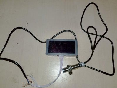
Hman (John Herrmann) had a brilliant suggestion of replacing the original speedo with a Hall-effect tachometer. They’re under $20 delivered off eBay; read out from 10-9999 RPM’s. John’s suggestion, since my saw is a 16” saw, was to put 4 magnets on the wheel so the readout would see 4 “blips” per revolution instead of the normal 1. The blade circumference is 16” x pi (3.14159) or about 50.25”. Dividing the circumference by 4 (for 4 magnets) gives a spacing of ~12.6” between the magnets. Sure, 12” would yield a readout of exact feet per minute, but I’ll live with the 5% error.
Digital tach for <$20 off eBay. Uses a Hall-effect pickup and magnet.
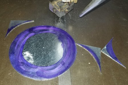
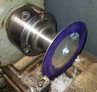
I started by making a mounting plate for the tachometer. Material was 16-gauge galvanized sheet metal. I rough band sawed it to size and punched a 3/8” hole through the center. A 3/8” bolt was used as an arbor and the disk was turned round on the lathe.
Dykem'd the 16-gauge stock and rough cut to shape
3/8" bolt for an arbor, pecked away on the lathe to clean up the edge
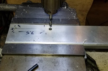
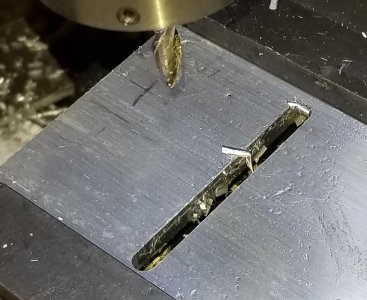
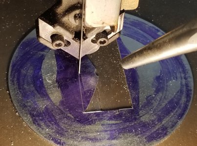
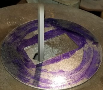
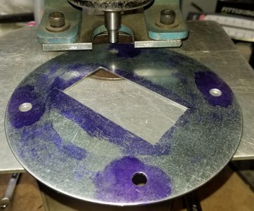
The disk was Dykem’d and the mounting hole for the tachometer was scribed on the blank. Now, how to cut out the hole? I have a Roper Whitney #218 punch press and could have gone that route, but instead used the DoAll. My saw has a blade welder, cut a 10’ length of ¼” x 32 tpi blade, fed it through the center hole in the blank and welded the blade. I rough cut the hole, split the blade at the weld and used a die filer to finish the hole. I used the RW #218 and a 5/16” punch to knock in 4 mounting holes.
Feed the blade through the center hole with TEETH DOWN so the scribed pattern was on top
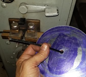
Welded, annealed, ground and re-annealed the blade
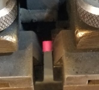
Ready to knock out the center hole
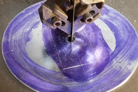
Last cut
Filing to fit
Punching in four 5/16" mounting holes
Next was mounting the magnets to the back side of the wheel. The Hall-effect tach’s work with a magnet. The sensor “sees” the magnet go by its tip, does some math, and indicates RPM’s. My plan (thanks again John!) was to mount 4 magnets so instead or reading RPM’s, it’s reading increments of 12.6” or very close to feet per minute.
Sharpie marked the magnet locations. Used a caliper to mark the distance from the edge of the wheel though I suspect the Hall-effect sensor tolerance is pretty big. The instructions said the magnet should be between 1mm - 10mm from the sensor.
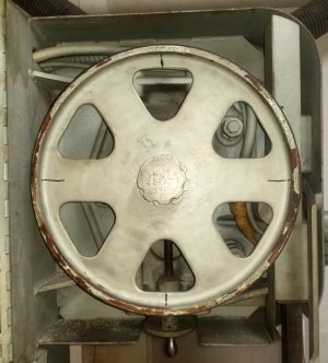
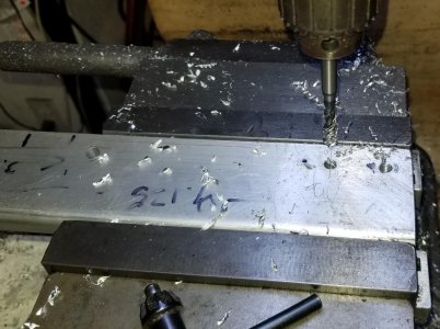
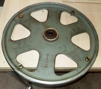
Used some 5/8” hex brass to make some mounting nuts for the magnets. Simple lathe work here: Face, center drill, #7 tap drill, ¼”-20 tap, countersink the end with a 5/16” end mill, bore to diameter/depth and part. The nuts were flipped and chamfered on the side that butts up to the wheel as they were very close to a fillet on the wheel. Drilled and tapped ¼”-20 holes in the wheel, ran in cap screws, Loctite’d the nuts in place and secured the magnets with Loctite.
Faced and center drilled
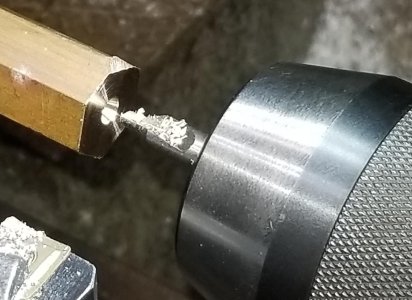
Tap hole
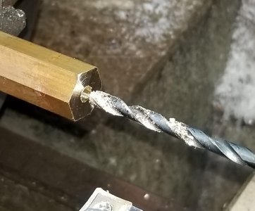
1/4"-20 tap
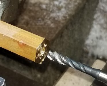
Countersinking with a 5/16" end mill
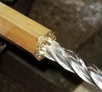
Bored to size and checked fit
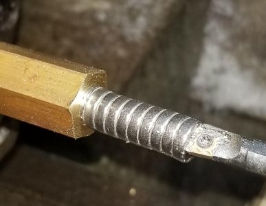
Parting
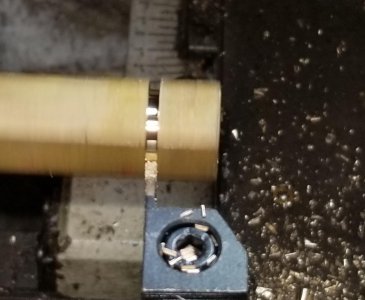
Flipped and chamfered the back side as the nut was just into the fillet on the perimeter of the upper wheel
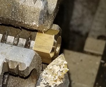
Finished nuts
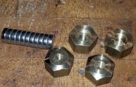
Magnet nuts and magnets were Loctite'd in place
Picture limit reached, so on to page 2 . . .
My saw came with the standard automotive-type speedometer with graduations in feet per minute. I knew the speedo wasn’t working when I bought the saw, I could see the needle in the bottom of the gauge. I finally got around to looking it over, I believe someone had it apart before and lost the steel disk used to magnetically couple the input shaft and the needle shaft. It’s not a serviceable part from DoAll though I could buy a replacement speedo for $1000!
Stock speedo needle shaft was broken

Hman (John Herrmann) had a brilliant suggestion of replacing the original speedo with a Hall-effect tachometer. They’re under $20 delivered off eBay; read out from 10-9999 RPM’s. John’s suggestion, since my saw is a 16” saw, was to put 4 magnets on the wheel so the readout would see 4 “blips” per revolution instead of the normal 1. The blade circumference is 16” x pi (3.14159) or about 50.25”. Dividing the circumference by 4 (for 4 magnets) gives a spacing of ~12.6” between the magnets. Sure, 12” would yield a readout of exact feet per minute, but I’ll live with the 5% error.
Digital tach for <$20 off eBay. Uses a Hall-effect pickup and magnet.

I started by making a mounting plate for the tachometer. Material was 16-gauge galvanized sheet metal. I rough band sawed it to size and punched a 3/8” hole through the center. A 3/8” bolt was used as an arbor and the disk was turned round on the lathe.
Dykem'd the 16-gauge stock and rough cut to shape

3/8" bolt for an arbor, pecked away on the lathe to clean up the edge

The disk was Dykem’d and the mounting hole for the tachometer was scribed on the blank. Now, how to cut out the hole? I have a Roper Whitney #218 punch press and could have gone that route, but instead used the DoAll. My saw has a blade welder, cut a 10’ length of ¼” x 32 tpi blade, fed it through the center hole in the blank and welded the blade. I rough cut the hole, split the blade at the weld and used a die filer to finish the hole. I used the RW #218 and a 5/16” punch to knock in 4 mounting holes.
Feed the blade through the center hole with TEETH DOWN so the scribed pattern was on top

Welded, annealed, ground and re-annealed the blade

Ready to knock out the center hole

Last cut

Filing to fit

Punching in four 5/16" mounting holes

Next was mounting the magnets to the back side of the wheel. The Hall-effect tach’s work with a magnet. The sensor “sees” the magnet go by its tip, does some math, and indicates RPM’s. My plan (thanks again John!) was to mount 4 magnets so instead or reading RPM’s, it’s reading increments of 12.6” or very close to feet per minute.
Sharpie marked the magnet locations. Used a caliper to mark the distance from the edge of the wheel though I suspect the Hall-effect sensor tolerance is pretty big. The instructions said the magnet should be between 1mm - 10mm from the sensor.

Used some 5/8” hex brass to make some mounting nuts for the magnets. Simple lathe work here: Face, center drill, #7 tap drill, ¼”-20 tap, countersink the end with a 5/16” end mill, bore to diameter/depth and part. The nuts were flipped and chamfered on the side that butts up to the wheel as they were very close to a fillet on the wheel. Drilled and tapped ¼”-20 holes in the wheel, ran in cap screws, Loctite’d the nuts in place and secured the magnets with Loctite.
Faced and center drilled

Tap hole

1/4"-20 tap

Countersinking with a 5/16" end mill

Bored to size and checked fit

Parting

Flipped and chamfered the back side as the nut was just into the fillet on the perimeter of the upper wheel

Finished nuts

Magnet nuts and magnets were Loctite'd in place

Picture limit reached, so on to page 2 . . .
Last edited:

