Didn't think it would work.

Razzle

Jack of All, Master of None
H-M Supporter Gold Member
Joined
Jul 22, 2013
Messages
130
I recently replaced the igaging scales on my minimill with glass scales. Using touchdro and the results are fantastic. Should have done it years ago. But what to do with the old scales. Ah, I can put them on my Lathe. A Logan 820. But it's 10x24 and the longest scale from my minimill is only 18. Should I just live with the limits to the travel? And then I remembered.
I cut down the 24" scale to fit the x axis of the mill. And I still have the cutoff piece. Would it be possible to rejoin the two and get a functional scale for the lathe?
Well, some small holes drilled, two wire pins and some jb weld later. Tada, back to one piece. But does it still work? With a little judicious filing and sanding I remounted the read head. Hooked it back up to the iGaging readout and started running it back and forth over the join. And can you believe it? I can't find a bobble, jump, skip, or lost position at all. It's not mounted to the lathe yet. And I intend to put the join at the tailstock end since 99% of my work is up front. So I won't hit that spot much. But I can keep the full travel of my lathe and get dro.
Now, I don't know if the fact that this works speaks to my 'phenomenal' work putting the scale back together or the cr@ppy nature of igaging scales and the bizarre processing they do to smooth out the bumps. But I suspect that if I hooked this up to a touchdro I might see something different. Hmmm, now where did I put that old DIY touchdro board........
 
Last edited:
what kind of programing or mod do you have to do to the touch dro to change to glass scales? I have the Touch Dro on my lathe for many years now I built it from the plans BUT am lost at the programing. someone on the forum walked me through it.
 
As far as alignment goes, the most you would be out would be half the scale resolution which would be 5 microns or .0002". It is possible that you could have damaged the capacitive element on one or both trimmed ends but I would expect that the pickup uses multiple elements in counting pulses so the change in pulse height may still be large enough to register a count.

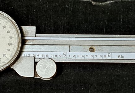
My first caliper was a Craftsman dial caliper. It used a rack and pinion to rotate the dial and one of the teeth in the rack was damaged just past the 5" mark. I cut the rack at the damaged tooth and cut a small section of rack. Using the small section, I carefully filed the two remaining sections so they mated with the small section. Then I installed the main section of rack back in the caliper and using the small section for alignment, installed the remaining section and clamped it in place. Then, using the mounting holes in the beam as a drill guide, I drilled new hole and removed the section and drilled clearance holes and counterbored for the two mounting screws. The result was a repaired caliper. A check with my 4" and 5" micrometer standards that bridge the repair reads a difference of 1.000".

The splice is shown in the photo below at 5.07".
Caliper Repair .JPG
 
@Ed ke6bnl Yuri has an excellent how to on using glass scales with the igaging adapter. https://www.touchdro.com/resources/adapters/32-bit/using-quadrature-encoders.html
There is no programming necessary as that adapter uses the universal firmware. You do need to wire in level shifters as the glass scales are 5 volt and igaging uses 3 volts.But the level shifters are cheap. And you need DB9 female connectors. You also need a different case. I just purchased and modified an electronics project box. But you could also 3d print one. Most of the existing touchdro cases aren't big enough for the additional hardware. I could have designed one and 3d printed it but I was too impatient as my 3d modeling skills are pretty slow.
@RJSakowski That sounds like good news. Nice to know that something similar has been done successfully before. Honestly, being 2 tenths out after 18" of travel on my old Logan would be invisible. Just having the Dro on the lathe is going to be a game changer for me. I have yet to build larger dials for it and working to tight tolerances is a skill still being developed. This should help.
The error should be consistent in any case. You can clamp a block to the table just before your splice and zero a test indicator against it. Then insert an accurately measured block so you are on the other side of the splice. By comparing the DRO reading against the measured block, you will have your correction.

If the error is significant to work you're doing, you will want to know exactly where the error occurs but that shouldn't be too difficult to determine, If you move the first block to half the distance and repeat, you can determine whether or not you have moved past the splice. If so, move the block back half that distance. If not, move the block forward half that distance. Each iteration will get you closer to the splice. If the measured block is 1/2", 10 iterations will locate the splice within .0005"
 
Back
Top