Dayton 5K453B to Dayton 2X440A Drum Switch dilemma.

73HEMIRR

Registered
Registered
Joined
Apr 2, 2022
Messages
10
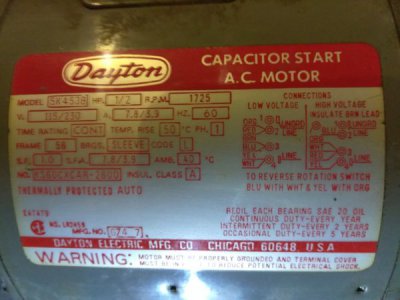
Trying to install a drum switch to my newly acquired Craftsman 101-21400 Lathe. I'm reaching out for help because I'm not a motor expert. The motor plate states to change directions of rotation you must swap Blu with White and Yellow with Orange. I've never had a motor where you had to swap 4 wires to change rotation.

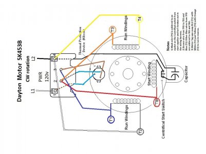
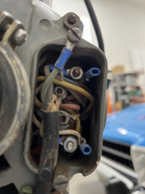
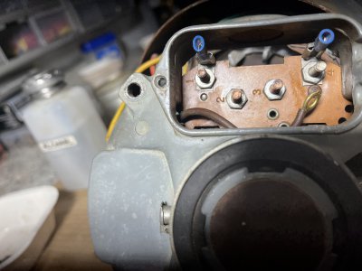
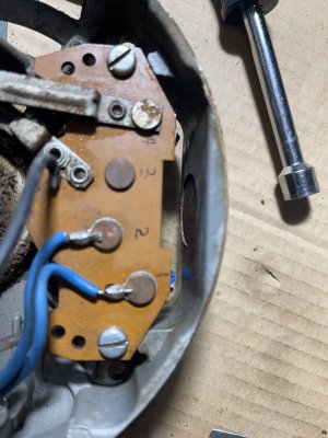
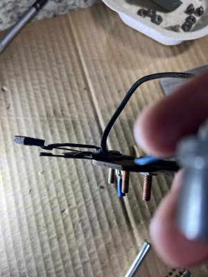
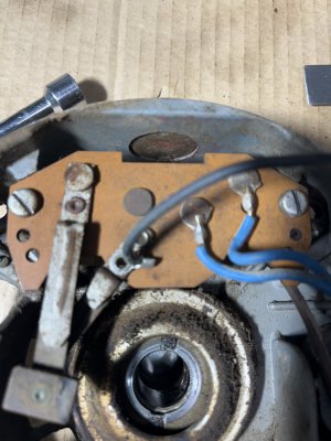
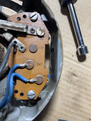
Ok, now that you know I have a "dazed & confused" look on my face and scratching my head. Here's the way I'm think the motor is wired. ref diagram, motor plate and pix. I just can't figure out how to wire to the Drum Switch (Hockey style) because the start circuit (Black wire) is soldered to the TB board/centrifical start switch and Capacitor. The motor was wired for 110v at which I want to keep.
thx. in advance.
73HEMIRR (Paul)
 

Attachments

  • Dayton 5K453B Label.jpg
    Dayton 5K453B Label.jpg
    47 KB · Views: 12
  • Lathe Motor wiring CW rotation.jpg
    Lathe Motor wiring CW rotation.jpg
    155.6 KB · Views: 13
  • IMG_8307.jpg
    IMG_8307.jpg
    177.4 KB · Views: 7
  • IMG_8318.jpg
    IMG_8318.jpg
    344.7 KB · Views: 3
  • IMG_8317.jpg
    IMG_8317.jpg
    256 KB · Views: 9
You lucky guy, you have a Dayton motor LOL:confused 3:
Let me take a look and I'll return momentarily
Edit: Deleted incorrect content
 
Last edited:
You lucky guy, you have a Dayton motor LOL:confused 3:
Let me take a look and I'll return momentarily
Paul you'll need to go behind the terminal board and bring the red and black wires out
(disconnect black from terminal 4 and red from terminal 2 and extend out to drum switch)
Connect the blue, white, yellow and orange as per the dataplate
Then you would wire it like this: (swap red and black as necessary for proper direction)
View attachment 408683
Mark,
thx. for the prompt reply. Here's my question. Since the Black wire does not attach directly to Term 4, It is soldered to the points of the Centrifical Switch coming from the Start Capacitor and makes contact with Terminal 4 when closed. If I unsolder the Black wire from the points of the Centrifical Switch and run it out to the Drum Switch won't that isolate the Centrifical Switch from the start Circuit. What am I missing?
 

Attachments

  • IMG_8320.jpg
    IMG_8320.jpg
    190.8 KB · Views: 2
  • IMG_8316.jpg
    IMG_8316.jpg
    244.7 KB · Views: 2
  • IMG_8317.jpg
    IMG_8317.jpg
    256 KB · Views: 1
Last edited:
Ah, I see. The centrifugal switch is part of terminal 4. I was going by your drawing and didn't look closely enough at the other pictures.
There is an alternate way we could do this
I'll do another sketch-
Try this: You bring out the Red wire and the Yellow and White as shown- should work
Blue, Brown and Orange connect as per the dataplate- swap Red and Term 4 at drum switch as needed to invert rotation
-M
DaytonMod2.jpeg
 
Last edited:
Ah, I see. The centrifugal switch is part of terminal 4. I was going by your drawing which doesn't represent the physical connections.
Are the blue, white, yellow and orange all accessible from the outside? There is an alternate way we could do this
-M
Yes, all wires I have access to.
thx.
Paul
 
I've seen this before with Dayton units- for ease of manufacture they make the centrifugal switch physically part of the terminal board which makes it difficult to bring out the entire start circuit (start leg) on a pair of wires
Obviously they don't intend the motor to be easily reversed
 
Ah, I see. The centrifugal switch is part of terminal 4. I was going by your drawing and didn't look closely enough at the other pictures.
There is an alternate way we could do this
I'll do another sketch-
Try this: You bring out the Red wire and the Yellow and White as shown- should work
Blue, Brown and Orange connect as per the dataplate- swap Red and Term 4 at drum switch as needed to invert rotation
-M
View attachment 408729
I will give that a try and report the results.
thank you so much.
Mark,
Worked perfectly on the trial run. I'll clean up the harness and install the motor and drum switch on the lathe. Hopefully I'll have the lathe cleaned up and ready to make chips fly.

Thx. again for sharing your knowledge.

Paul
 
Back
Top