- Joined
- Oct 30, 2019
- Messages
- 225
At a recent auction I picked up a Dake #1 Arbor Press as an upgrade to my Dake #0 that only saw occasional use, but at least once I wished I had more capacity.
The price was right, after fees/taxes it came out to $100 - but this thing has definitely seen its decades of use in production.
I don't have any "before" pictures except the auction listing picture itself, since I didn't expect this to end up being an interesting (to me) set of tasks, but ...
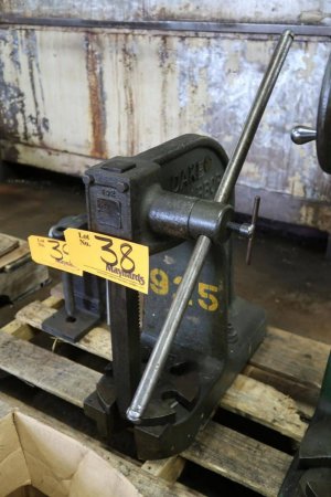
What you can't tell from the picture above:
- The table, under all that grime, has been cracked and brazed back together
- The center hub/pin feature in the table is missing, so it just sits on the foot of the press without having that center indexing point. I have a feeling that when it was damaged and brazed back together, the pin was broken off or misaligned and so they torch or plasma-cut the center out of the table, quite crudely. My bet is that the press fell over at some point and the table took the hit, probably saving the rest of the press mechanism.
- The table has a lot of wear/tear, I think from key broaches making contact with the slots in the table
- The cross-hole in the spindle hub, where the handle slides through, is egged out substantially.
None of these really impact function, but:
- I wanted to bore out the middle of the table and put a new hub/pin feature in it
- Due to the prior braze repair, it didn't sit 100% flat on the foot of the press. This was a good chance to skim cut the front and back after having a new hub+pin as a reference plane
- I started cleaning and lubricating the spindle and rack/pinion -- one thing led to another and, well...
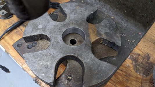
First here's the last few steps of the table repair. Here is the table after I bored out the middle, since it had only been crudely torched out before.
Then I made a new press-in hub out of a piece of scrap, with the 1/2" center pivot point in the back
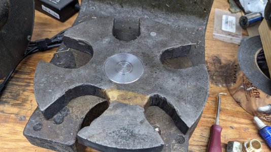
Then I held it by the pin in the 4-jaw chuck and skim cut the front:
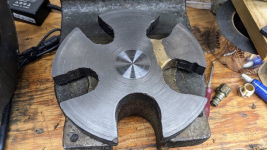
Finally, I held it in the chuck with the now-flat front surface pressed against the jaws, and skim cut the back so it would be parallel to the front, perpendicular to the pin, and sit flat in the bottom of the press
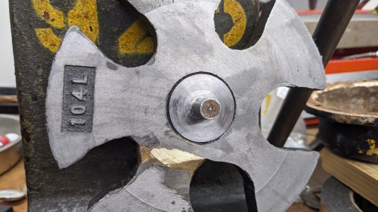
I ended up getting a better surface finish on the back once I rotated to a new cutting edge on my insert and adjusted the feedrate, but oh well. Just skimmed it enough that it sits flat, you can see a low spot near the braze. No reason to chase that out.
-----
Once I started taking apart the main rack/pinion mechanism, I couldn't resist the desire to bore out the cross hole for the handle and press a sleeve in. The fit was incredibly sloppy. The handle is nominally 3/4" (.740 as far as I could tell), and surprisingly not bent at all. The cross-hole was ugly, I don't have before pictures but it was at least .850-870" in its widest dimension, egged out really badly with a huge burr built up on one side and a smaller one on the other. I think this was used in a production pipeline by the prior owners, so it saw a lot of repetition with load on one side of the spindle and a narrow range of motion, making the wear noticeably asymmetric between the opposing sides of the bore.
This was a number of firsts for me:
- I have never used a boring head/bored holes on a mill
- This Bridgeport has only been in my shop for 5-6 months
- I just bought a used boring head 2 months ago but aside from some test chips on my smaller mill I haven't used it yet
- This was a perfect chance to use the boring head as well as the power quill on the Bridgeport
After putting the spindle/pinion through the ultrasonic cleaner, I put it in a V-block with a piece of aluminum flashing to protect it from the clamping screw, and set to work boring it out.
I algned it by putting the handle in it and tightening the retaining screw, and using a level to make it sit vertically. I don't have a coaxial indicator yet, but also the hole is so egged out I don't think it would have helped a huge amount. I put the gearbox in neutral and turned the mill spindle by hand to just skim the two narrower sides, and center it up.
Then I took light passes until it cleaned up almost the whole way, giving a final diameter of 0.880"
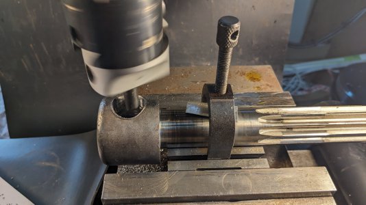
You can see the huge burr on this side of the cross-bore, from all the egging/wear.
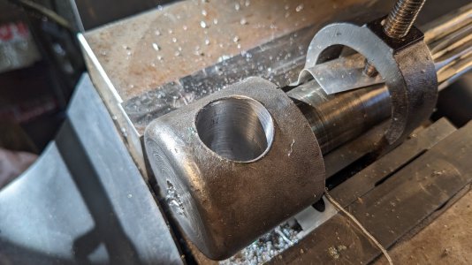
I didn't get pictures of making the sleeve but it's nothing special. If this was a vise spindle, I would have used a steel sleeve but being an arbor press in a home shop I figured bronze or brass would be nice. The only thing I had on hand that was large enough (1" diameter or larger, since I needed a press-fit into 0.880 which is over 7/8") was a piece of oilite bronze bearing material.. not the worst choice for this application.
Due to the oil weeping out of the bronze, I did clean it off with a bit of brake parts cleaner before applying green locktite when pressing it in. That said, the press fit was tight enough that locktite was 100% unnecessary in this application.
I was shooting for a .002" press fit but ended up slightly larger than that, like .003 or .0035". since the arbor press was the patient in question, I pressed the sleeve in with the bench vise, then put the entire spindle/pinion in the collet chuck in the lathe to clean up the sleeve ends.
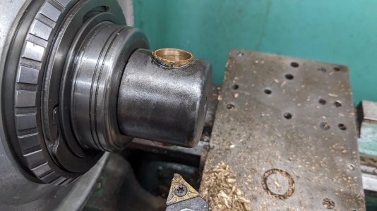
I ended up skimming the hub of the spindle overall, about .005 to .010" removed to just barely clean it up, take the big steel burrs off, and take the excess sleeve material out.
This borders on over-restoring but no other part of this is a restoration so it doesn't count. The OD of the hub isn't critical and wasn't 100% concentric with the pinion shaft features originally, so my .005-.010" skim cut just barely cleaned that up to make it concentric (there's one portion that it barely rubbed instead of taking a chip, and I left it there instead of removing more material unnecessarily)
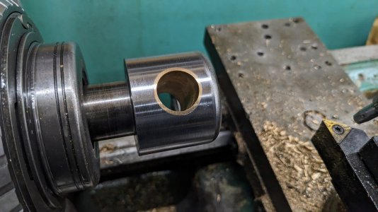
Can't complain about the result
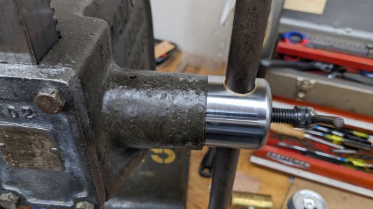
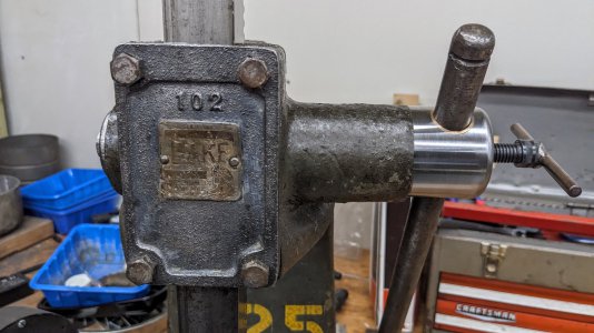
I cleaned a bunch of the parts, but not the main casting since I was going for functionality-centric cleaning, lube, and minor repairs.
Thanks for reading
The price was right, after fees/taxes it came out to $100 - but this thing has definitely seen its decades of use in production.
I don't have any "before" pictures except the auction listing picture itself, since I didn't expect this to end up being an interesting (to me) set of tasks, but ...

What you can't tell from the picture above:
- The table, under all that grime, has been cracked and brazed back together
- The center hub/pin feature in the table is missing, so it just sits on the foot of the press without having that center indexing point. I have a feeling that when it was damaged and brazed back together, the pin was broken off or misaligned and so they torch or plasma-cut the center out of the table, quite crudely. My bet is that the press fell over at some point and the table took the hit, probably saving the rest of the press mechanism.
- The table has a lot of wear/tear, I think from key broaches making contact with the slots in the table
- The cross-hole in the spindle hub, where the handle slides through, is egged out substantially.
None of these really impact function, but:
- I wanted to bore out the middle of the table and put a new hub/pin feature in it
- Due to the prior braze repair, it didn't sit 100% flat on the foot of the press. This was a good chance to skim cut the front and back after having a new hub+pin as a reference plane
- I started cleaning and lubricating the spindle and rack/pinion -- one thing led to another and, well...
First here's the last few steps of the table repair. Here is the table after I bored out the middle, since it had only been crudely torched out before.

Then I made a new press-in hub out of a piece of scrap, with the 1/2" center pivot point in the back

Then I held it by the pin in the 4-jaw chuck and skim cut the front:

Finally, I held it in the chuck with the now-flat front surface pressed against the jaws, and skim cut the back so it would be parallel to the front, perpendicular to the pin, and sit flat in the bottom of the press

I ended up getting a better surface finish on the back once I rotated to a new cutting edge on my insert and adjusted the feedrate, but oh well. Just skimmed it enough that it sits flat, you can see a low spot near the braze. No reason to chase that out.
-----
Once I started taking apart the main rack/pinion mechanism, I couldn't resist the desire to bore out the cross hole for the handle and press a sleeve in. The fit was incredibly sloppy. The handle is nominally 3/4" (.740 as far as I could tell), and surprisingly not bent at all. The cross-hole was ugly, I don't have before pictures but it was at least .850-870" in its widest dimension, egged out really badly with a huge burr built up on one side and a smaller one on the other. I think this was used in a production pipeline by the prior owners, so it saw a lot of repetition with load on one side of the spindle and a narrow range of motion, making the wear noticeably asymmetric between the opposing sides of the bore.
This was a number of firsts for me:
- I have never used a boring head/bored holes on a mill
- This Bridgeport has only been in my shop for 5-6 months
- I just bought a used boring head 2 months ago but aside from some test chips on my smaller mill I haven't used it yet
- This was a perfect chance to use the boring head as well as the power quill on the Bridgeport
After putting the spindle/pinion through the ultrasonic cleaner, I put it in a V-block with a piece of aluminum flashing to protect it from the clamping screw, and set to work boring it out.
I algned it by putting the handle in it and tightening the retaining screw, and using a level to make it sit vertically. I don't have a coaxial indicator yet, but also the hole is so egged out I don't think it would have helped a huge amount. I put the gearbox in neutral and turned the mill spindle by hand to just skim the two narrower sides, and center it up.
Then I took light passes until it cleaned up almost the whole way, giving a final diameter of 0.880"

You can see the huge burr on this side of the cross-bore, from all the egging/wear.

I didn't get pictures of making the sleeve but it's nothing special. If this was a vise spindle, I would have used a steel sleeve but being an arbor press in a home shop I figured bronze or brass would be nice. The only thing I had on hand that was large enough (1" diameter or larger, since I needed a press-fit into 0.880 which is over 7/8") was a piece of oilite bronze bearing material.. not the worst choice for this application.
Due to the oil weeping out of the bronze, I did clean it off with a bit of brake parts cleaner before applying green locktite when pressing it in. That said, the press fit was tight enough that locktite was 100% unnecessary in this application.
I was shooting for a .002" press fit but ended up slightly larger than that, like .003 or .0035". since the arbor press was the patient in question, I pressed the sleeve in with the bench vise, then put the entire spindle/pinion in the collet chuck in the lathe to clean up the sleeve ends.

I ended up skimming the hub of the spindle overall, about .005 to .010" removed to just barely clean it up, take the big steel burrs off, and take the excess sleeve material out.
This borders on over-restoring but no other part of this is a restoration so it doesn't count. The OD of the hub isn't critical and wasn't 100% concentric with the pinion shaft features originally, so my .005-.010" skim cut just barely cleaned that up to make it concentric (there's one portion that it barely rubbed instead of taking a chip, and I left it there instead of removing more material unnecessarily)

Can't complain about the result


I cleaned a bunch of the parts, but not the main casting since I was going for functionality-centric cleaning, lube, and minor repairs.
Thanks for reading
Last edited:

