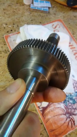
Cutting Gears. Diametral

Ray C

Registered
Registered
Joined
Nov 16, 2012
Messages
5,596
Part 1:

I need to cut two gears for a project so, here's a write-up on it. I'll explain what I'm doing and toss in a little "gear talk" along the way. One gear needs to be 32 tooth the other 80 tooth. I'll be using a metric gear cutter but, because I'm more familiar with SAE formulas for gears, I will convert the metric size to SAE and use the SAE formulas. There's nothing wrong with doing this and you still end-up with a proper gear.

Most common gears have a "involute" tooth shape. This means that as two teeth engage each-other, the point along the surface of engagement moves in a smooth, circular-like motion. Furthermore, common gears have a pressure angle of either 14.5 or 20 degrees. The pressure angle is determined by the involute shape of the surface of the tooth. When one gear turns another, two forces are at-play. One force transmits power to the other gear and is a useful force. The other force pushes one gear away from the other along a line through their center-points and does not contribute toward spinning the other gear. The angular sum of those two forces results in the pressure angle. 20 degree PA can transmit more power but, makes more noise when operating. 14.5 degree PA gear will transmit power less efficiently but, operate quietly.

For this project, I want small profile teeth to keep the size of gears small and I have a metric gear cutting set in a small size. Much like the differences between SAE vs metric nuts & bolts, gears are either SAE (Diametral Pitch) or metric (Modulus) based. There are standard formulas for gear cutting. The method of doing the math for SAE vs metric is a little different because SAE gears are measured by teeth per inch and metric uses millimeters per tooth. Fortunately, you can convert the formula techniques because 1 inch is 25.4mm.

Most standard SAE size gears (from small to large) are 24, 22, 20, 18, 16, 14, 12, 10, 8, 6, 4... teeth per inch (TPI). Standard metric (modulus) gears from (small to large) are 1, 1.5, 2, 2.5, 3, 3.5, 4, 4.5, 6... millimeters per tooth.

SAE Diametral Pitch = 25.4 / Metric Modulus. Conversely, Metric Modulus = 25.4 / SAE Diametral Pitch

You cannot intermix SAE and metric gears just as you cannot intermix SAE and metric nuts & bolts. If two gears are to be used together, they must be either the same Diametral Pitch or Modulus.

The smallest cutting set I have is a modulus 1 (metric) size. I much prefer to work with SAE (diametral pitch) formulas so, I simply convert the size from metric (Module) to SAE (Diametral Pitch). SAE Diametral Pitch = 25.4/Modulus and in this case that's simply 25.4/1 = 25.4 If I had a Modulus 2 size profile, Diametral Pitch would be 25.4/2. etc...

EDIT FOLLOWS:
When the diametral pitch is 25.4, that means for every 1 inch of circular distance around diameter across a shaft, you will have 25.4 teeth. So, 25.4 teeth packed into 1 inch of space means the teeth are pretty small. If I were using SAE cutters, the next closest standard size to 25.4 would be a 26 DP gear; meaning, for every 1 inch of circular linear distance, there would be 26 teeth. They look similar but will destroy each-other if used together.

In part 2, we'll talk about how to calculate stock sizes and cutting depths...

Part 3 will talk about how to use the correct gear within a set of gears.

Part 4 will be step-by-step instructions on fixture setup and actual gear cutting.


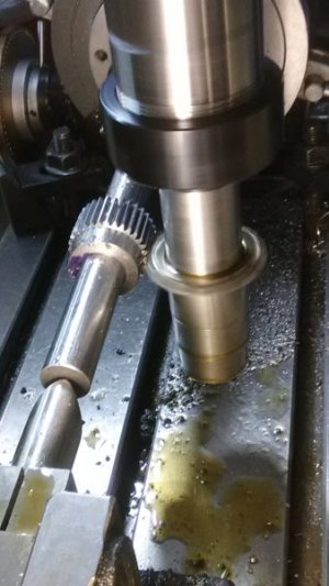
Stay tuned. Here's a preview of the grande finale...
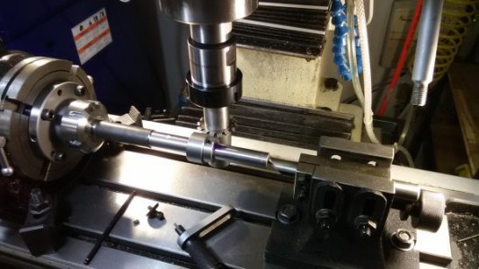
IMG_20180506_144759.jpg


Ray

EDIT: I corrected a misstatement diametral distance after reading brino's question. -My bad.
 
Last edited:
Me to Ray. Been wanting to learn this for awhile now.
 
Part 1.5 (Part 2 will come sometime later this evening).

There was some commentary about the terms "Diametral" and "Modulus" from the first post. Furthermore there was an indication that the SAE (society of automotive engineers) had nothing to do with gears. Let's clear this up...

The term "Diametral" and "Diametral Pitch" is used on virtually every page in the chapter pertaining to gears in the Machinists Handbook. Also, the term is used for both US-standard and metric gears. Similarly, the word "Modulus" (in both plural and singular tense) is also used throughout the pages pertaining to gears in the Machinists Handbook. If you have ever read Machinists Handbook or other standards-based documents (from either ISO or AGMA) you will notice universally that US-standard sized gears refer to the base size and type of gear using the terms Pitch or the inferred "Diametral Pitch". Similarly, if someone has ever read an engineering standards document from ISO, or read about metric gear standards from the AGMA, you will universally notice that the base size of metric gears is defined by the term "Module" or "Modulus" (one is the plural of the other).

And finally, until 1966, the US Department of Defense formally recognized the SAE (society of automotive engineers) as the official standards keeper for splines and gears. The AGMA has been around for a long time but, in the late 60's when metric gears first started to become more common-place in the USA, the US DoD began to recognize the AGMA. Currently, to the best of my understanding, there is no one single standard for all gears by all nations.

Most of the books I have (from my father and uncle) about gears were written in the 40's and 50's. My main resource is a book from the SAE titled:
SAE Standards, Specifications and Formulas for Gears.

I hope this clears-up any confusion and passes-on knowledge (in a polite and respectful way) that this site is known for.

Regards

Ray C.
 
Part 2:

Stock Diameter:

When cutting a gear, the stock diameter must be calculated so the teeth fit evenly around the circumference. Two things are needed to make this calculation, the Pitch Diameter and the Addendum. Both are very easy to calculate -and easy to understand their physical representation.

Pitch Diameter is simply Number of Teeth divided Diametral Pitch. What is confusing is that sometimes people mix-up the terms Pitch Diameter and Diametral Pitch. Be careful when reading and using these terms. They mean very different things.... Since I want to make a 32 tooth gear, pitch diameter is 32/25.4 = 1.2598.

What is Pitch Diameter? Assume you had two round wheels and you wanted them to spin with a specific ratio when they came into contact with each-other. This is easy... the ratio is just the ratio of the diameters. Gears are a little different. The teeth need a little extra height so they will engage properly. If you take two properly meshed gears from a system and grind the tops of the teeth off in equal amounts from both of the gears just until they touch but won't mesh enough to transmit power then, the resulting diameter will be the Pitch Diameter. The Addendum is the amount needed to grind from the tops of the teeth to reach the pitch diameter.

Because of the design of all involute style gears, the Addendum is related to the Diametral Pitch as: Addendum = 1 / Diametral Pitch.

The moment you've been waiting for:
  • Stock Diameter = Pitch Diameter + (2 x Addendum height).

For the32 tooth gear, stock diameter is 1.2598 + (2 x 1/25.4) = 1.3385"

Depth of tooth cut:

There are 2 formulas, one for fine pitch gears and one for coarse pitch. Fine pitch (small teeth) is considered to be 20 teeth per inch or more. Coarse is fewer than 20 teeth per inch.

The last and final moment you've been waiting for:
  • Depth of tooth cut for fine pitch is: (2.2 / Diametral Pitch) + 0.002
  • Depth for coarse pitch is: 2.157 / Diametral Pitch
For the 32 tooth gear, depth is: (2.2/25.4) + 0.002 = 0.0886


Summary for 32 tooth gear:

Summary for 32 tooth gear with modulus 1 tooth pitch (equivalent to a 25.4 tooth per inch diametral pitch gear):
  • Starting Stock Diameter: 1.3385"
  • Each tooth cut to depth: 0.0886"

Calculations/Summary for 80 tooth gear:

Stock Diameter: Pitch Diameter + (2 x Addendum height).
  • 80/25.4 + (2 x 1/25.4) = 3.2283"
  • Tooth depth (same as 32 tooth gear): (2.2 / Diametral Pitch) + 0.002 = 0.0886"

So... If someone buys a metric "modulus" based gear cutter set and wants to make a gear using the formulas usually used on US-Based, SAE Diametral Pitch gears... now you can do it.

Regards

Ray C.
 
Ray,

Thanks for the write-up. I appreciate you sharing this.

There is one part that confuses me and I am hoping that you can clear it up.

In both posts #1 and post #5 you use the term "teeth per inch" when talking about gears. I don't understand that.
I am accustomed to talking TPI with threads, that fine.....and I could see using TPI for a rack, as that would be much like a thread.

But when it comes to spur gears what does "teeth per inch" mean?
With the thread and rack I can picture the linear inch measurement and counting the teeth.
For a spur gear do I need to wrap a flexible tape measure around the OD and count teeth?

Or is it "teeth per inch of diameter"?
Or something else entirely.

Thanks for any light you can shed.
-brino


You're welcome. I had fun writing this.

TPI: It's the Diametral ratio -not linear distance. For every 1" of diameter, you'll have 25.4 teeth. As diameter increases, the number of teeth increase according to that ratio. That is what "Diametral" means.

BTW: The corollary in metric gears is the Module but the terms of the ratio are reversed. -Thus, there are two sets of mathematical techniques; one for US/SAE gears an one for Metric. In this post, I've only shown the US/SAE method of doing things.
Ray
 
Part 3:

Why do gear cutters come in a set for a particular Modulus or Diametral Pitch?

To preserve (as much as possible) the Involute shape on a gear tooth, each cutter in a set has a slightly different profile shape to accommodate gears with small numbers of teeth vs large numbers of teeth. Each gear in the set can cut gears over a specified range with a given number of teeth. For this example, for the 32 tooth gear, a size #5 cutter will be used. The 80 tooth gear needs the size #7 cutter.

If someone wanted a perfectly matched set of gears for totally optimal operation, a special cutter with a unique involute profile would be needed for each gear with a given number of teeth. -Not practical... and thus, the cutter designers decided on the best trade-offs between performance and practicality and grouped standard cutters into a fixed set.

A typical breakdown for a Module 1 set (and most other metric and SAE styles) is shown here but, always look at the gear cutter itself. The range it can cut will be engraved in the side of the cutter.

Size 8: 135 - Rack
Size 7: 55 - 134 teeth
Size 6: 35 - 54 teeth
Size 5: 26 - 34 teeth
Size 4: 21 - 25 teeth
Size 3: 17 - 20 teeth
Size 2: 14 - 16 teeth
Size 1: 12 - 13 teeth

For size 8, it says Rack. That means a straight line of gears as in a Rack & Pinion setup.

Once again, when you're making gears that mesh, they need to be cut with cutters of the same Diametral pitch or metric modulus.

One thing I've always wondered (and don't know the answer to) is when designing a gear system with gears of different sizes, if it's best to try to chose the gears such that the teeth needed on the gear falls, for example, into the middle-range of the cutter's ability. I wonder if such parametric or (mathematically) transcendental logic has any benefit...

OK... next and final part will be setup and action shots... Stay tuned.

Ray
 
Setup, setup, setup. Check, double check and triple check.

If a gear is to come out nicely, everything along the way needs careful setup.

Some blow-by-blows...

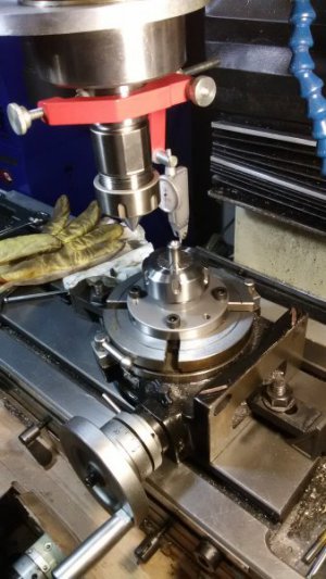
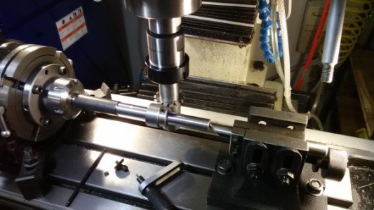
I used to have a little 3 jaw chuck mounted on this rotary table but I gave up on it and went with this ER40 setup. This was the first time it was being used, so I mounted a freshly turned and precisely center-drilled piece of stock and verified the chuck was centered. At every step along the way, all measurements were indicated to within 1/2 thou.
IMG_20180506_083136.jpg

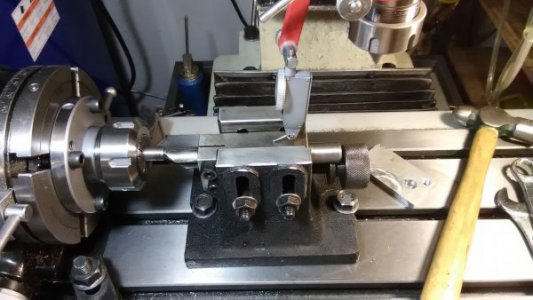
Here, the tailstock is set into center hole and the indicator is making sure the tailstock is flat by running back/forth in the X direction. If it's not flat, it will cause problems later on when you tighten the tip in the center-hole.
IMG_20180506_085604.jpg


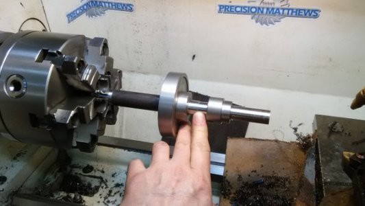
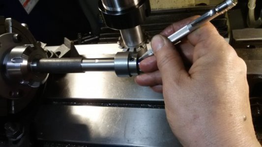
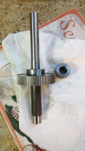
Always make a good fitting shaft to hold the gears while they're being cut. That shaft fits both the gears which have different ID holes. A step was put in the shaft so each gear could butt-up against a shoulder. The fit to that shaft was perfect. A little hard to get on by hand but not a force fit. Don't make the shaft too long or it will flex when cutting. Don't make it too short or your cutter will be cramped for space. FYI: Each gear also has a set screw on the collar to keep it pinned to the shaft while cutting.
IMG_20180506_131456.jpg

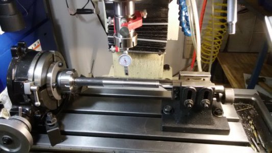
To align the rotary table, the tailstock is not inserted into the center hole yet. Tighten the chuck on the shaft then run the table back/forth in the X direction and adjust the rotary table until it's perfectly perpendicular to the shaft.
IMG_20180506_141304.jpg

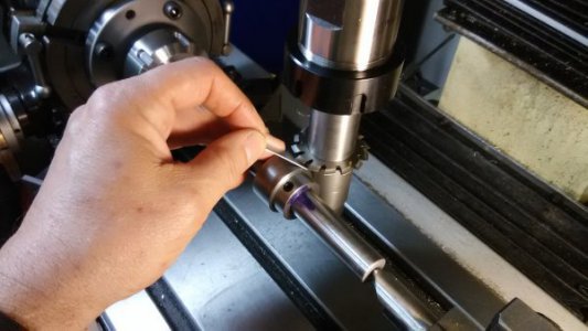
Once the shaft is perfectly straight, the gear blank can be installed. Next, keep a dial indicator on the part then, draw the tailstock tip into the center hole, making sure the shaft is not getting pushed off of alignment. In this picture, I forgot to show the indicator.
Notice that the shaft and gear blank are installed so the cutting force pushes the piece into the shoulder of the shaft. It will be game-over if you don't get that right.
IMG_20180506_144759.jpg

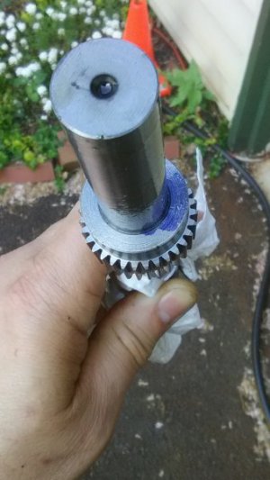
To be on the safe side, I like to make a witness mark. Check it once in a while so you can throw the gear away as soon as you notice it has slipped out of position.
IMG_20180506_183942.jpg

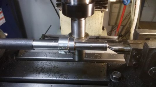
Now you have to find the center for the cutter. Set the piece close to the cutter in the Y direction then zero the Y scale. I use a piece of stainless steel foil and slowly lower the head just until it pinches the foil. If you use paper, it's too easy to crush the paper so I prefer the foil I use for heat treating wrap. Next (not shown), move the part out of the way in the Y direction, lower the cutter below centerline then, put part back at the Y0 position. Do not rotate the cutter while repositioning the cutter below center. Doing so will change the distance of the point from the piece and invalidate your initial Y0 reading. Raise the head until the edge of the cutter pinches the foil. With top and bottom known, centerline distance can be set.
IMG_20180509_171414.jpg

It's all clear sailing after this. I make extensive use of the DRO and table stops when doing this. I touch-off the part, set the DRO to the calculated depth then, cut the first tooth. After that, I set the table stop to prevent stupid mistakes.
IMG_20180509_181515.jpg

It's really nice when that last tooth is cut and it fits in the remaining empty space just right. -Big relief. -Actually, there is no guess work at all. On the rotary table, ink marks are made at the holes on the hole-plate where the pin will land. The only reason for a surprise at the end, is if the part slipped.
IMG_20180509_184941.jpg

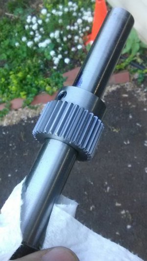
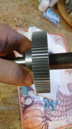
So far, so good... Looks nice all the way around.
IMG_20180509_185551.jpg IMG_20180509_185617.jpg

Looks even better close-up.
IMG_20180509_190059.jpg

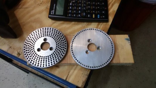
A custom hole plate was made and used for this project. (Obviously, it's the one on the right).
IMG_20180507_210553.jpg

So, there you have it. I'm almost done with the 80 tooth gear and pictures will be posted when it's done. After that, I'll return to the the other thread where these gears are going to be used for the Z axis on the mill. https://www.hobby-machinist.com/threads/power-z-conversion-for-pm45.69552/

So, I'll be back later...

Let me know what you think and if you have questions. We can talk about using the Rotary table if that's useful for anybody.


Ray

PS: If anyone has a comment like "In my 73 years of owning a machine shop, I've never seen such a stupid way of doing things"... please don't ruin this thread and take it offline in a PM so I don't have to delete your posts again.
 
Last edited:
Here's the last few action shots of the second gear.

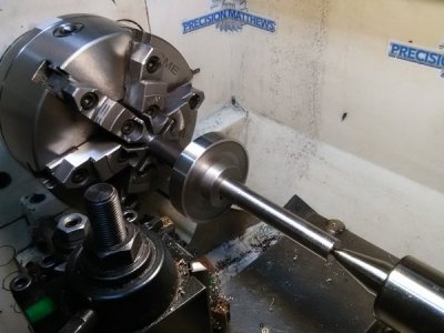
Taking it to final size before cutting teeth. Also, you can see the step on the shaft a little better, which was used for the other gear.
IMG_20180510_185805.jpg

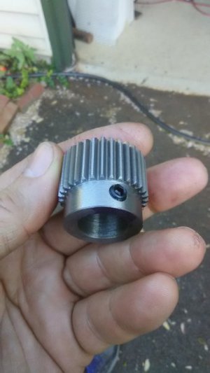
Obligatory eye-candy... The line on the left side of the right picture coincides with the recess on the side of the gear. I'm guessing there was difference in the vibration characteristics as the cutter went over that area. You can see it under the right light but can't feel it it's only on the root. The face is smooth.
IMG_20180512_064258.jpg IMG_20180512_064331.jpg


It's a keeper.
IMG_20180512_064423.jpg

Now to go back to the Z axis drive project...

Ray
 
Last edited:
Back
Top