Yep I'm back haha. Jim and DERF have been great help in the past so I though I'd see if you can get me over this hurdle. Hopefully I can make CNC chips by christmas.
This has been a long time in the making. But I finally got some time to play with it and getting the wiring figured out. I got Linux CNC on a desktop and playing a little with it.
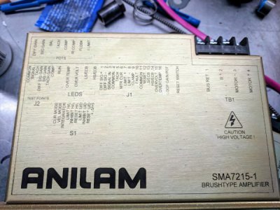
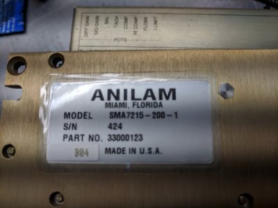
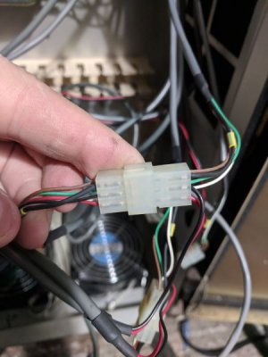
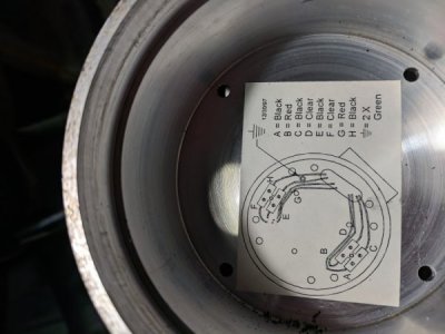
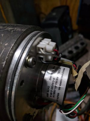
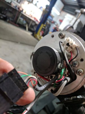
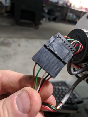
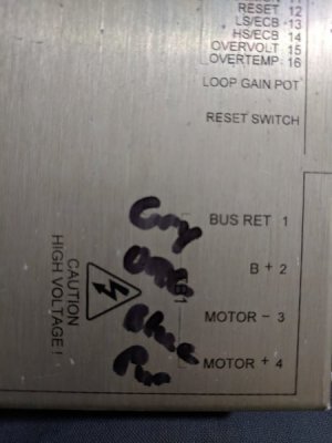
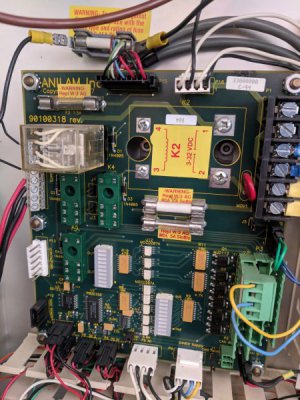
I think I have figured out the encoder portion, just trying to figure out the drive control now and having a little trouble deciphering how this all works. I am reusing the Anilam drives SMA7215-1. I have attached pictures of how they were wired in with the Anilam set up. I'm not finding how I should rewire them to the 7i77. Any help on this would be great.
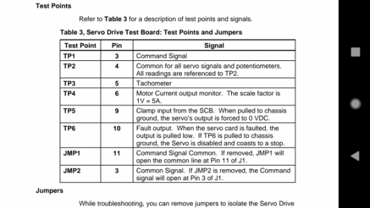
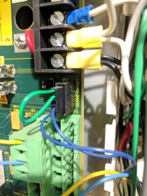
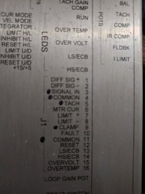
On the drive, there is a 16 pin connector in the middle on the right side. only pins used in past configuration were 3. Signal IN, 4. Common, 5. Tach, 9. Clamp, 11. Common.
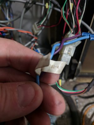
The 3. Signal in is a red wire coming from the Anilam console, the 11. Common is black from the console. 5. Tach is a red wire going to the servo, paired with 4. Common black wire. 9. Clamp is a blue wire that goes to an Anilam board plug that says Servo Inhibit.
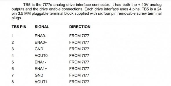
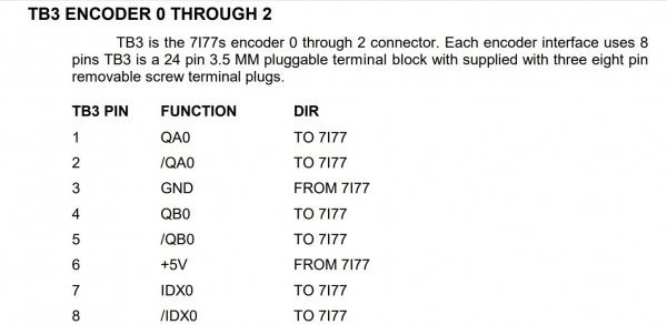
These are the pins I don't really understand. I know something from the 7i77 should hook to these. The available inputs are listed in the pictures. My Choices are ENA0-, ENA0+, GND, AOUT0,
Pictures attached, thank you in advance!


 Mounted it on the inside of the door.