- Joined
- Mar 16, 2020
- Messages
- 10
Good evening everyone,
So I decided to jump head first into building a cnc router, never have and now its gonna be sink or swim.
I will be using a chinese 1400mm x 900mm frame, powered by
Wantai SS880 drivers
Nema 34 12nm on the X
Nema34 9nm on the Y & Z
3x 350w 60v power supply
24v power supply
5v power supply
220v 2.2k watercooler huanyang gt with braking resistor
AXBB-e with UCCNC software
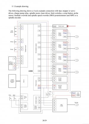
I have been working on my shop in the basement and haven't even built the frame, in the meantime I have been putting the electronics together and have been trying to figure out how the vfd will need to be wired in order for the spindle speed to be controlled by the uccnc software.
I have read the manual on page 29 and the wiring is somewhat different for the j1000.
In any case I would like to know if anyone has experience with the AXBB & Huanyang combo.
In the manual it specifies to take the jumper out to make the 5v outputs into 10v in order to control the vfd speed, other have mentioned that it's the opposite. Also I believe that the manual (and others online) says a relay for the vfd to even run is needed, well if where to change the pin to 10v would a 10v relay be needed for the vfd or still a 5v relay?
wiring diagrams or type of help would be greatly appreciated, I haven't found anyone online or YouTube talk about this.
I have included a pic of my controller "box"
And all criticism is welcome, constructive or not haha.
Thanks,
J


