CNC Newbie - making a Denford mill work

AR1911

Active User
Registered
Joined
Nov 5, 2010
Messages
871
I bought a Denford Micromill 2000 this week. This is an English product built around a Sherline mill, using Denso steppers, and all the electronics built into the back of the cabinet. It is made to be used with the proprietary software, which is $675. I don't want to do that.
All I really want at this point to connect it to a PC (RS232) and run some simple software to verify it works. However, I keep running into "Change the servos, toss the Denford board to use a generic breakout board, and run Mach3". I don't really want to double the cost of the machine, knowing it's not much more than a toy anyway.
My question is, why do I need to change the servos, or the board? Do all these machines/servos/boards speak a different language? Am I missing something here?


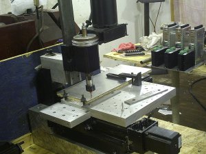
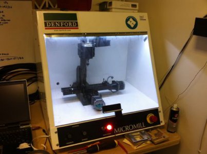
This isn't my mill (first photo). Mine has the high speed air spindle, which I guess is best used for engraving.
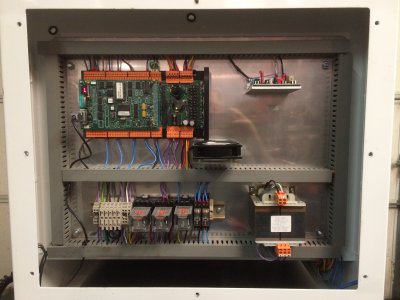
The 2nd photo is the back of my cabinet.
500px-Denford.JPGIMG_4121.JPG

500px-Denford.JPG IMG_4121.JPG
 
the board on it is proprietary and I have never found a way to bypass it, there may be a way but I could not do it.
I have the same mill and the lathe and I converted them to mach3 pretty cheap
a tb6560 board and a 12v power supply
you can use the original stepper motors but larger would be better
and you would be surprised what that mill can build if you add a 1.5kw air cooled spindle but even with the original in brass and aluminum it will work pretty well. adding a coolant system works miracles
I used mine to make all the parts to convert my zx45 mill to cnc.
http://www.hobby-machinist.com/showthread.php?t=8187&page=9&highlight=zx45
steve


attachment.php?attachmentid=39980&stc=1&thumb=1&d=1397491722.jpg
 
You kind of opened a can of worms here. Yes it's possible to connect to the RS232 port and run a simple program to test the machine. The problem is that you don't know what the command strings between the controller and the PC look like. If you had a copy of the original software it would be easy to look at the command strings, then you could write a simple program that would output those strings. A bit of a Catch22 situation.

It could be that just sending G-code commands from a console program like HyperTerminal might work if sent in the format that is in the manual. I would give that a try. I suspect it won't work, but you might get back some control characters that be helpful in decoding the communications.


This is an interesting but difficult problem.
 
Steve, that TB6560 board looks like the least expensive way to go. I may just order one and then try to figure out how to connect it. Did you buy the power supply also or just use something you had on hand?

- - - Updated - - -

Jim, are you saying that the original board takes G-code from the software and converts it into proprietary language to run the servos, or vice-versa? I'm struggling to understand why, if they all use G-code, what makes the boards and software incompatible? I ran into the same thing with an Emco a couple years ago.
 
Jim, are you saying that the original board takes G-code from the software and converts it into proprietary language to run the servos, or vice-versa? I'm struggling to understand why, if they all use G-code, what makes the boards and software incompatible? I ran into the same thing with an Emco a couple years ago.

Yes. Each motion controller has it's own proprietary OS or firmware, none that I know of will take G-Code in directly and run a machine.

The following is a simple G0 (Rapid) move from my CNC controller program running on the PC.

The G-Code generated by a CAM program, or manual input,

G0 X0.0176 Y-0.652

is translated to position and velocity variables that the motion controller can understand, values are in Pulses per Inch. It also tells the motion controller to execute the move.

XPOS=447;YPOS=-16561;ZPOS=0;VSRAPID=42333;XQ#G0,3|10

Then this code on the motion controller is executed to actually make the move

#G0;CAS;LM XYZ;VVS=VSRAPID;L=XPOS-_RPA;M=YPOS-_RPB;N=ZPOS-_RPC
LI L,M,N<-1>(_VVS/4);LE;BG S;AM S;EN


As you can see it gets more cryptic as it gets closer to something the controller can read. In this case the motion controller could be running either stepper or servo motors depending on the configuration, but the code is the same.

The G-Code could be directly input to the controller board and all of the translation could be done there, but the problem is that there is very limited memory on board the controller which limits the amount of code space available. The motion controller OS is not very efficient at manipulating text strings so it is better to do it in an external program.

In my controller program, the entire G-Code file is translated and stored on board the PC when loaded. When you press the RUN button it is then fed to the motion controller as buffer space is available. I assume that this is pretty much how most of the systems work.

The program running on on the PC also provides the operator interface, normally including; DRO, a method of changing operational parameters, tool path view, and other functions needed for a user friendly operation.

Mach3 and a few others are interesting exceptions to this. In addition to providing the operator interface, they take the G-Code, and directly convert it to pulses per inch (or pulses/mm), then output a pulse stream to an interface board, through the PC parallel port, which then drives the stepper controllers. Mach3 is therefore a motion controller. The interface board is just really an optical isolater so that the parallel port of the PC is not directly electrically connected to the stepper drivers and limit switches. You could connect to the stepper drivers and limit switches directly to the parallel port without the interface board, not recommended but possible. Overall it works surprisingly well, at least until Windows decides to do something in the background then you may lose position.

I hope this makes sense.
 
Last edited:
Then this code on the motion controller is executed to actually make the move

#G0;CAS;LM XYZ;VVS=VSRAPID;L=XPOS-_RPA;M=YPOS-_RPB;N=ZPOS-_RPC
LI L,M,N<-1>(_VVS/4);LE;BG S;AM S;EN

I just got a Denford Microturn 2000. I'd plan on replacing the controller but I hope to use the original steppers and their drivers. First, though, I'd like to make sure that the steppers, drivers and spindle are operational. If I can use the RS-232 interface directly from a computer, maybe I could convince myself that these parts don't need to be replaced.

I'm thinking that if I had the initialization message(s) the PC sends the Denford and a couple of simple instructions like move and spindle energize, I could do this test. So, the code you've posted is very interesting. Is your instruction above exactly what is transmitted on the RS-232? Can I just send this info via a terminal and get rapid movement to the XPOS, YPOS and ZPOS positions? Do I need to provide values for RPA, RPB, RPC? What about spindle control? Are there instructions that precede the G0 command?


I also have a microMill and from testing I know the drivers are destroyed but I've verified that the steppers work by testing them with the one cheap stepper board I already have. For this simple test, I used a version of the Arduino based rotary controller in this thread http://www.hobby-machinist.com/showthread.php?t=20120 to rotate the steppers. For my next step, I've ordered additional cheap driver boards to see if I can mate them to the original steppers.

Regarding AR1911's original question, do you think he could use this same method to assure himself that his steppers/drivers are operational before he starts investing in improvements? If he's happy with the capabilities of the Denford steppers and drivers, he might find the most cost effective solution is to just buy a break out board.


One small problem with the above code snippet, it is not Denford code. It is Galil Motion Control DMC code that I use in my system. I was just providing a generic example of the normal system architecture to answer AR1911's question about motion control boards in general.

Unfortunately, I have no idea what the Denford command strings look like. It wouldn't be hard to figure out, but would require the original Denford software, then just look at the data passing between the PC and the controller.

The least cost method would be to buy a cheap stepper driver board, a breakout board, and download the free evaluation version of Mach3. Based on the picture above, it looks like the power supply is in place so that would not have to be purchased. I'm guessing the cost would be less than $100. It might be possible to access the Denford stepper drivers directly and use them, but I don't think it would be that easy. I'm sure they are integrated into the overall system.

Sorry I can't be of more help.
 
Thanks for the response. I was hoping to find some short Denford RS-232 snippet just to test the components.

You're probably right about finding the point to insert the step drive and direction signals. Accessing the steppers themselves has been easy enough but I haven't gone the next step. So to speak.
 
Steve, that TB6560 board looks like the least expensive way to go. I may just order one and then try to figure out how to connect it. Did you buy the power supply also or just use something you had on hand?

I also purchased a 24v power supply. sorry for the slow reply I'm not getting my email notifications here again?
steve
 
Have not had a chance to work on this since my post.
I have this breakout board, CNC4PC C11 Rev 5, and a PC with a parallel port and Mach3.
Will this board work?
What else do I need?

Yesterday I acquired yet another Sherline CNC mill, this one is a Lab-Volt 5400. From my initial research, it appears this one might be easier to interface with. I may be able to test it later today.
 
Back
Top