- Joined
- Mar 22, 2017
- Messages
- 9
Recently I saw several YouTube videos of guys who figured out how to use their CNC mill as
a lathe with gang tooling. I have an IH CNC mill (now Charter Oak) so I quickly got very interested in this, since the price of a CNC Lathe was totally out of the question. It was fascinating to watch, but they did not provide enough information on just how they did it. One guy said he did this using Mach3 and had to write macros to make it work. Some of them wrote the Gcode by hand. There was never enough information in these videos. Sounded way to complicated.
I spent a lot of time on Google searching for information. I quickly learned that the CAM software starts
and $1000. Then there was the problem of figuring out just how these guys got Mach3 Turn to work since it
does not have a Y axis. I found two posts with critical clues. Fusion360 by Autodesk appears to be the best bet for the CADCam software for my needs. The second software is MSM Mill Turn by Calypsoventures. This becomes the interface with Mach3 with the ability to set Y axis offsets very easily. The only other mill turn software I found was MasterCam Mill Turn. Prices start at $4000. I will be testing both MSM Mill Turn and Fusion360 software within the next week or two.
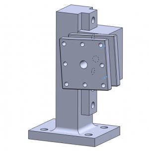
Having selected the potential software for this project, I just completed the preliminary design for the tooling
to make this all work. Attached is CNC Lathe.pdf that will show the setup. This is version 1.0. I hope to get some feedback to make this even better in version 1.1.
With the impressive 22" Z travel axis on the IH mill, I will have the capability to have a usable 9" of material length to work with. I will be using an 1" ER collet for the material holding. The gang tooling is set up to be able to turn up to 3" in diameter. With a 3" 3 jaw chuck with an r8 spindle, I will also be able to turn up to 3" pipe as well.
Here are the cost estimates for this project.
Fusion360 $0.00
MSM Mill Turn $0.00
(both software packages allow free use to hobbyists)
7 piece lathe turning tools $100.00
3" 3 jaw Chuck with R8 $100.00
3 1/2" Jacobs Chucks $30.00
Materials $50.00
Total $280.00
Not a bad price for a CNC Lathe!
Feedback?

