- Joined
- Dec 20, 2021
- Messages
- 1,048
This project starts back a ways, have a Synchronome master pendulum clock that needs to get hung up. They're fairly well known clocks, and were typically used to drive slave clocks in an office building, banks etc. As with any pendulum clock, they do better on a solid foundation. Solid being massive concrete foundation of a building or similar.
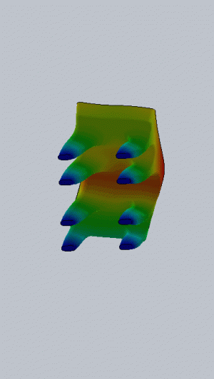
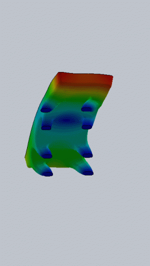
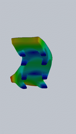
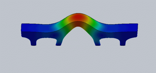
My workshops in the house have a good concrete foundation, but it's all buried behind an insulated stud wall and 1" of blue board. To tie into that, the wall needs an opening, and concrete extended out. So, why not over engineer it? Build a concrete base with legs extending off the wall. The idea is to insulate behind it, and the smaller surface area of the legs will reduce heat loss.
I've got a couple future projects that will be based on concrete poured into a form. So this seems like a good chance to test out the theory of milling a form, and casting concrete into it. A little cad work, an 8 legged base design with good mass and a flat surface were sketched up. The idea being the blue board will only be removed where the feet will contact the wall. The spray foam the rest of the area underneath.
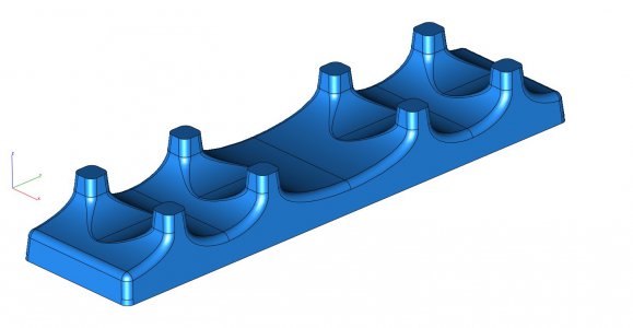
Of course, the CAD is the easy part. The next step was to laminate up 3 layers of 2" blue board. That turned out harder than expected. Solvent based glues melt the foam. Water and alcohol based glues won't dry. Epoxy is too hard, and busts foam while milling. Eventually gorilla glue was settled on. The problem is that needs water to kick it off. So the trick was to wipe the foam board down with a damp rag before applying the glue. Then a little tape and a lot of full toolboxes for ballast to keep is pressed together. (No images)
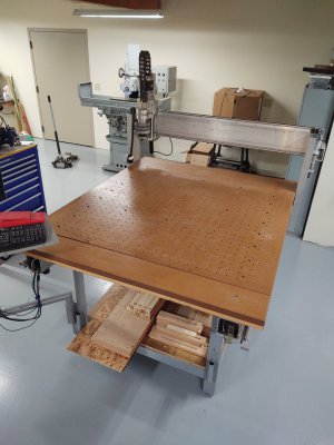
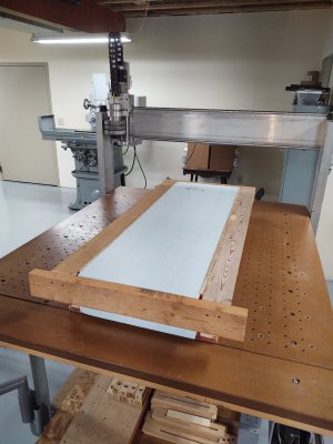
Cleaning the router table took three days! That was a royal pain! Everything that I didn't want to deal with for the last 3 years landed on it. It's mostly sorted out thrown out now. Also had to raise the gantry to the top position, it's adjustable for stuff like this.
Once that was done, built a frame. Didn't expect the foam would hold up to 150lbs of wet concrete without backing. Form was pretty simple, just a little scrap OSB and 2x4. (See that one stud, that looks twisted on the right side? That bugger has been kicking around the garage for over a decade. Finally flattened a side and put it to use!)
Then came the part that shouldn't have been hard. Getting a long reach large diameter ball end mill. Looked on line, $140! No way! Finally decide to mill foam it would be easy enough to just make one. Started with a ball end shape in cad, rotated it 5 degrees in two planes and projected it to a flat surface. Brought that back up, and added some lead in and out for the milling operation.
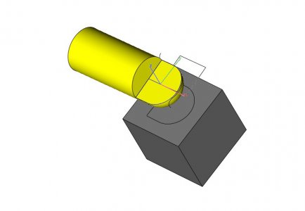
Next was taking some 4130 tube, milling off half, welding up the hole, grinding some clearance and TIG welding a few old drill bits onto it. Ground the hard edge back down to flat like a D bit. Mounted it in a collet block, and rotated the flat and the block to match the double 5 degree rotations in cad. Then milled the ball end shape.
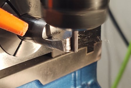
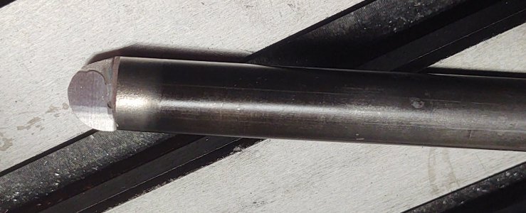
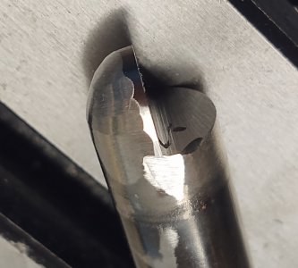
A little hand clearance grinding and it cut foam.
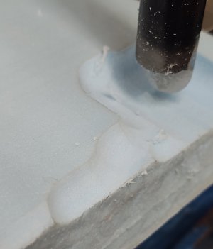
Thinking about it, became a little worried about running a home made bit at 8000-10,000 RPM. So epoxied an old carbide shank inside the tube near the collet end. Carbide being stiffer should take up some of the bending load, and stiffen the tube for the collet to grip it. Chucked it up, and tweaked the runout of the bit to be mostly zero against the cheap Chinese spindle and collet. Typed in 8000 RPM and hit go... sounded good.
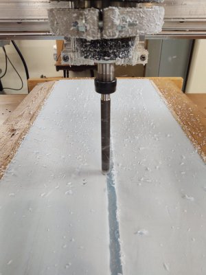
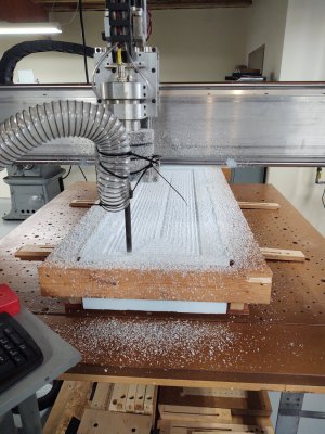
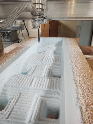
The next Saturday revolved around chasing little blue dust bunnies with a shop vac, emptying the vac, and repeating. The last image was the start of the finishing pass. that was broken up into a waterline finish, and a few other zigzag passes to clean it up.
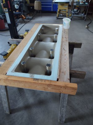
After that, some quick sanding, then paint, then sand, then paint then... (No in process images, just wanted to get it done! ). To protect the foam and reinforce it, layered most of the outside with 3M packaging tape. Also taped over the bottom holes of the form where the legs end, and painted that too. This would keep the concrete from sticking to the OSB underneath. Quick layer of bondo below the feet on that board to help support the tape. The tape was mostly to prevent the form from wanting to split, and make cleanup and troweling the surface easier. That worked great! No damage to the top edge of the form.

3D Printed a few parts. Washers and spacers to hold some conduit (bolt clearance) and a steel washer, and a form for bolt head relief. The head relief form was printed with 1/4"-20 threads, and a bolt came through the form bottom and bolted up the whole thing.
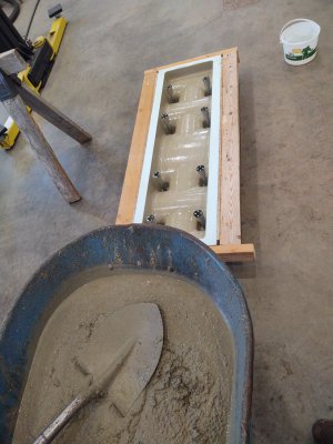
Mixed up some mud, and poured it. A bit after midnight it was finally set up enough to try to finish the surface. Turned out OK. Left it in the form for another two days.
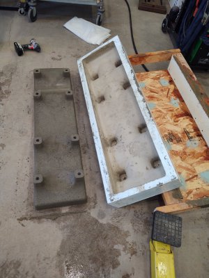
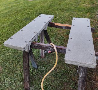
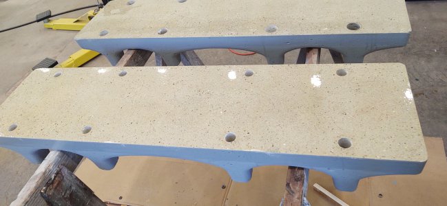
Then finally popped it out. Came out easy, the 5 degree draft angle did the trick. Pulled most of the bolt clearance forms (Two are stiff, gonna leave them until the mud it set more). Set some cardboard down, 5 mill poly sheet, and set the concrete on that. Wrapped it up, poured a gallon of water on it, and sealed it up. I'll let it sit like that for a few weeks, keeping it wet the whole while. Then let it dry out, and start finishing it up.
My workshops in the house have a good concrete foundation, but it's all buried behind an insulated stud wall and 1" of blue board. To tie into that, the wall needs an opening, and concrete extended out. So, why not over engineer it? Build a concrete base with legs extending off the wall. The idea is to insulate behind it, and the smaller surface area of the legs will reduce heat loss.
I've got a couple future projects that will be based on concrete poured into a form. So this seems like a good chance to test out the theory of milling a form, and casting concrete into it. A little cad work, an 8 legged base design with good mass and a flat surface were sketched up. The idea being the blue board will only be removed where the feet will contact the wall. The spray foam the rest of the area underneath.

Of course, the CAD is the easy part. The next step was to laminate up 3 layers of 2" blue board. That turned out harder than expected. Solvent based glues melt the foam. Water and alcohol based glues won't dry. Epoxy is too hard, and busts foam while milling. Eventually gorilla glue was settled on. The problem is that needs water to kick it off. So the trick was to wipe the foam board down with a damp rag before applying the glue. Then a little tape and a lot of full toolboxes for ballast to keep is pressed together. (No images)

Cleaning the router table took three days! That was a royal pain! Everything that I didn't want to deal with for the last 3 years landed on it. It's mostly sorted out thrown out now. Also had to raise the gantry to the top position, it's adjustable for stuff like this.
Once that was done, built a frame. Didn't expect the foam would hold up to 150lbs of wet concrete without backing. Form was pretty simple, just a little scrap OSB and 2x4. (See that one stud, that looks twisted on the right side? That bugger has been kicking around the garage for over a decade. Finally flattened a side and put it to use!)

Then came the part that shouldn't have been hard. Getting a long reach large diameter ball end mill. Looked on line, $140! No way! Finally decide to mill foam it would be easy enough to just make one. Started with a ball end shape in cad, rotated it 5 degrees in two planes and projected it to a flat surface. Brought that back up, and added some lead in and out for the milling operation.

Next was taking some 4130 tube, milling off half, welding up the hole, grinding some clearance and TIG welding a few old drill bits onto it. Ground the hard edge back down to flat like a D bit. Mounted it in a collet block, and rotated the flat and the block to match the double 5 degree rotations in cad. Then milled the ball end shape.


A little hand clearance grinding and it cut foam.

Thinking about it, became a little worried about running a home made bit at 8000-10,000 RPM. So epoxied an old carbide shank inside the tube near the collet end. Carbide being stiffer should take up some of the bending load, and stiffen the tube for the collet to grip it. Chucked it up, and tweaked the runout of the bit to be mostly zero against the cheap Chinese spindle and collet. Typed in 8000 RPM and hit go... sounded good.


The next Saturday revolved around chasing little blue dust bunnies with a shop vac, emptying the vac, and repeating. The last image was the start of the finishing pass. that was broken up into a waterline finish, and a few other zigzag passes to clean it up.

After that, some quick sanding, then paint, then sand, then paint then... (No in process images, just wanted to get it done! ). To protect the foam and reinforce it, layered most of the outside with 3M packaging tape. Also taped over the bottom holes of the form where the legs end, and painted that too. This would keep the concrete from sticking to the OSB underneath. Quick layer of bondo below the feet on that board to help support the tape. The tape was mostly to prevent the form from wanting to split, and make cleanup and troweling the surface easier. That worked great! No damage to the top edge of the form.

3D Printed a few parts. Washers and spacers to hold some conduit (bolt clearance) and a steel washer, and a form for bolt head relief. The head relief form was printed with 1/4"-20 threads, and a bolt came through the form bottom and bolted up the whole thing.

Mixed up some mud, and poured it. A bit after midnight it was finally set up enough to try to finish the surface. Turned out OK. Left it in the form for another two days.

Then finally popped it out. Came out easy, the 5 degree draft angle did the trick. Pulled most of the bolt clearance forms (Two are stiff, gonna leave them until the mud it set more). Set some cardboard down, 5 mill poly sheet, and set the concrete on that. Wrapped it up, poured a gallon of water on it, and sealed it up. I'll let it sit like that for a few weeks, keeping it wet the whole while. Then let it dry out, and start finishing it up.

 And bonus points for finally beating that crooked 2x4 into submission!!