Clausing 5900 Quick Change Gearbox Disassembly

GrizzlyBagWorks

Registered
Registered
Joined
Jun 23, 2016
Messages
30
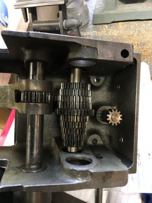
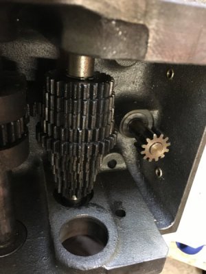
I've hit a roadblock on breaking down my Clausing 5914 QCGB. Can anyone advise what the proper steps are to complete the breakdown? My guess is to remove the nut on the main gear cluster and then drive it out in the direction of the bearing cover. Once that cluster is out the key is removed from ABC gear selector and the shaft is driven out.

If you have expierence in this I'd love to hear your thoughts. I'm hesitant to brute force anything without certainty as to what the next steps should be.

Thanks!

 
I rebuilt my 5914 QCGB about a year ago, have some sketchy notes and a few pictures. Its definitely a tight fit in there, kind of like taking apart a 5-speed transmission.

Some info is here (not mine):
http://hobby-machinist.com/threads/clausing-5418-lathe.38010/

My notes:

5900 QCGB dog clutch shaft (ABC selector):
Bearing 044-039 (also called 6202-5/8, also called 6202 15.875 also called 6202 15.88) measures 1.378 OD x 0.562 ID .431W
6202-10 has special 5/8" ID, but would require .032 wall thickness sleeve (better)
Shaft is 9/16 (.563) with 1/2-20 nut on one end. Locktite blue.

5900 QCGB cone gear shaft (feed selector)
Bearing 044-022 (both sides) Appears that 6202-10 are direct replacement.
Shaft is 5/8 (.625) with 5/8-28 nuts on each end.
Grainger/Zoro has NTN 6202LLB/15.875C3/L627
Use nuts to align cone gears (make sure everyting is centered in different gears) then locktite in place (red). Original was heavily staked.

Clean threads on shaft ends using appropriate die.
Sand shafts so bearings just slide on.
Use 1" iron pipe to drive bearings into QCGB housing.

Lead Screw shear pin: 0.093" brass rod (3/32" diam).

I probably should have taken more pics but got a bit greasy in there, and I wanted to get the firty job done.

Once you get some of the bearings pulled off there will be some slop between the shafts that will let you move things around better. Its a tricky fit, and complicated by the fact that the bearings were likely pressed onto the shafts. I made mine a sung sliding fit on reassembly.

Good luck!
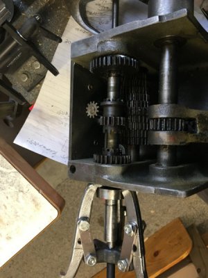
qcgb_disassembly1.jpg

qcgb_disassembly2.jpg

qcgb_disassembly3.jpg
 
Last edited:
Thank you for the info! Very helpful. After looking at your photos and reexamining the exploded parts schematic I realized that there was a 1/2 bearing cover on the lead screw side of the sliding gear shaft. My gearbox was so grimey that I thought the shoulder I was looking at was part of the casting when it was in fact a cover. I took a rubber dead blow mallet and punched the shaft towards the lead screw side. Once the bearing was out there was room to slide the middle gear to the side and remove the key. With teh key out the shaft came out with ease.

For the main cluster I removed the nut on the non-lead screw side and gave it a few mallet blows towards the lead screw side. This popped the bearing cover off and exposed a 2nd nut. I removed that nut and then drove the entire shaft out on the non-leadscrew side. The smallest gear on the non-leadscrew side of the box is pressed on, the rest are held in place by the key. I kept the gear cluster in the proper order and orientation, zip tied them loosely and dropped them in a bucket of industrial purple.

I pressed out the bronze bushings on one of the sliding gears on one in the body of the gearbox and dropped that into the bucket of industrial purple as well. In ~16 hours the paint will completely dissolve off (diluted 1:1) and I can spray it down with prep n/ etch (3 water:1 prepnetch) to convert any rust to iron oxide. Then a quick wire wheeling, followed by an acetone wipedown, and it's ready for paint.

New bearings will be ordered shortly.

Hope that helps anyone that may be doing the same down the road.
 
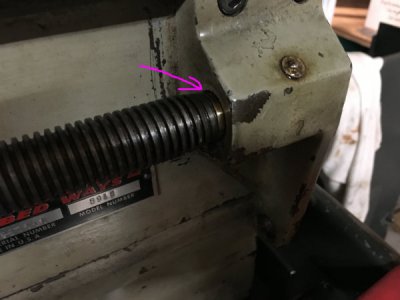
On my lathe the QCGB bearing that supports the leadscrew was pretty beat up. I decided to add a brass thrust bearing at the RH end of the leadscrew to take some of the force off of that bearing. Need to remember that these lathes were designed before carbide became popular, and the QCGB bearings are not that large. I also used double rubber sealed bearings throughout.

leadscrew_thrust_bearing.jpg
 
Last edited:
I have a Quick Change Gear Box that came with some parts that I purchased when I was restoring my 5914. The gearbox was disassembled years ago with the intent of rebuilding it. The bearings were bad and one shaft is galded. I just recently read these helpful posts and watched the video and it inspired me to get busy on this rebuild - now that I am retired and looking for fun projects.

Going through the manuals drawing -I account for all the parts except for the spacers shown on each end of the 9/16" Shaft. Part no's 699-094 and 699-091. I am guessing these are needed to locate the gears on the shaft away from the bearings and housing. They are NOT referring to the 1/32 Bushings used to reduce the bearing ID down to 9/16 are they? Are they Steel?

GrizzlyBagWorks - If by chance you still have your gearbox disassembled, would you mind taking some measurements of these two spacers.
Were you able to remove the old 1/32 sleeves and use them in your new 6202-10 bearings?
Thanks all.
Jim
 
Last edited:
Back
Top