- Joined
- Dec 18, 2019
- Messages
- 7,339
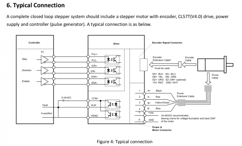
The manual isn't clear, at least to me. The typical connection looks incorrect in Figure 4. They have the collector of the NPN photo-transistor connected to the negative of a battery and have labeled it as COM-. The emitter seems to be the alarm signal. That would mean the collector is connected to positive and ALM would go to a load and then to ground. So I'd guess that the label should be COM+?

Anyone used this signal before and figured it out? I'm trying to work through a cable diagram for my ELS and wanted to add in this signal into the cables I make. I am not using the alarm at the moment, but when I button things up in a box, I would like the controller to be able to read this signal, since the little light will no longer be visible.
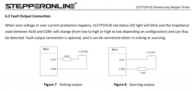
Figures 7 & 8 don't make much sense either, they don't seem to make sense with reference to Figure 4.

Can someone point me in the right direction?

Anyone used this signal before and figured it out? I'm trying to work through a cable diagram for my ELS and wanted to add in this signal into the cables I make. I am not using the alarm at the moment, but when I button things up in a box, I would like the controller to be able to read this signal, since the little light will no longer be visible.
Figures 7 & 8 don't make much sense either, they don't seem to make sense with reference to Figure 4.

Can someone point me in the right direction?
