- Joined
- Jun 15, 2018
- Messages
- 295
The original carriage lock setup in my lathe was far from perfect. In order to operate it I had to grab a 13 mm wrench and if unlucky, the gib adjusting nut did not allow locking until carriage was moved into a more suitable position. obviously this was a result of the chinese engineer not thinking.
In addition of being sometimes inoperable the lock nut was on top of the carriage collecting swarf and whatever into it's threads. The nut was also really flimsy and made of some soft iron.
The goal:
- no wrench should be needed to operate the lock
- the associated thread should be under the carriage to prevent it from collecting stuff
- the adjustment of the lock should be simple
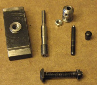
The locking block had a hole in the middle. This hole was not in the center (2mm off) and the bolt was a rattle fit. Further more the hole was too big in order to be able to first bore it in the center and then thread the M10 thread I was planning. Bored the hole up to 15 mm and threaded M16 x 1.0. Then made a bushing with similar thread out of tool steel. Some locktite and now I was able to hav my M10 thread inb the block.
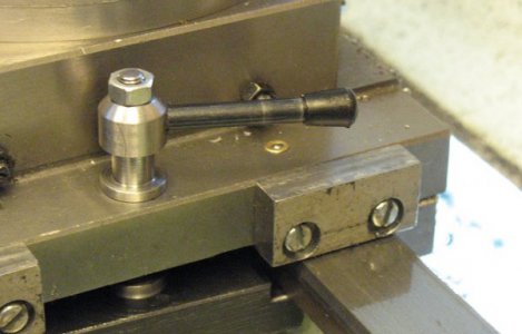
The lock bolt is no more a rattle fit which makes it so that when the carriage is not locked it does not bind every now and then. The original setup was binding even if the carriage was not locked because of the very loose bolt. The new bolt is made out of tool-steel and since I do not have a M10 die I had to do some single point threading. The new bolt also has a taper to jam the locking lever on top of the carriage. This lever has a matching taper.
Works lot better than the original. Installation was amazingly easy to do. I am happy with this. The original bolt is on the bottom of the picteure.


