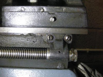
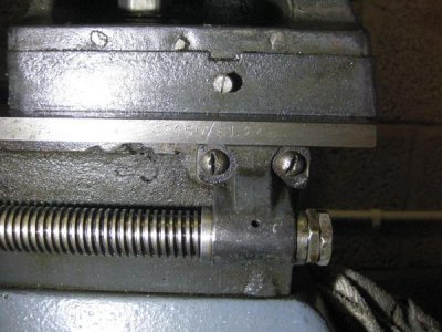
Carriage lock craftsman old style perhaps

Round in circles

Active User
Registered
Joined
Jul 9, 2014
Messages
613
Seeing as my lathe is similar to a 1940's Atlas lathe if anyone has one can they tell me what the carriage lock plate dimensions are

It appear that mine is a simple " U " bridge of cast iron looking material about 3/4 of an inch long by 1/2 an inch wide ( whether it is the correct one or not is a different matter ) with a bolt locked on at the top right hand side of the carriage and shaped on the underside nut that draws the U up to the bed underside .

The lock plate appears worn , in that the carriage tends to ever so lightly to try and slide to the opposite direction when I am using combination slide pushing towards the chuck, so I'm looking to make one .

Or
Am I wasting my time and need to rely on carriage/bed locks instead.
 
I ended up solving the problem by getting a lump of 2 x 2 x 1/4 thick angle iron by squaring the end with an angle grinder then scribing up a new plate 1 & 1/16 long by 7/8 wide . The old plate had the locking screw thread to one side this new plate I've made is still slightly to one side but not as much as the old one


I drilled the screw thread hole to tapping size and then scooped out a 9/16 wide U shaped channel in the plate so the edges of the U ran parallel to the bed of the lathe.
The two now raised lips run on either the carriage underside and on the underside of the lathe bed outer edge

This time I made the friction plate big enough so it was also riding on the toothed carriage rack so it could not rotate like the old one frequently did .

I've also confirmed what I've been thinking for a few weeks now , namely that the lathee is a through and through British made one .. all the threads are either BSF or Withworth and the grease cups are threaded in 1/8 Briggs grease nipple/ grease pot threads ( almost identical to a 1/8" gas thread . )

All the 1930's to 1980's American manufactured machinery including trucks & generators mainly those bits of kit on, " Lend lease ",that I've worked on all had American threads
So I doubt that the USA would have tooled up specifically in BSF for a small run of a thousand or so lathes bound for the UK in wartime.
 
I've found another interesting challenge this evening .
I decided I was going to play at setting up the lather for 97 threads per inch as auto feed so I could take off a few thou very slowly ( 67 RPM unbanalced off centre load ) without me having to keep feeding the tool post into the material for most of the metal removal exercise.

Once I'd got the hand book on the right page i discovered that there is an anchor bolt , nut and sleeve with stand off missing .. so I can't put the final 64 toothed gear in place and complete the gear train .
If I hadn't got the block of aluminium partly bored though on the face plate I would have instantly used the lathe to make a new sleeve and modified a " T " nut and shanked bolt , putting a metric thread on the end as I don't have any BSF nuts to hand , though I will try & make some at a later date now that I have some BSF taps & a suitable set of thread gauges ).


Question:-
I want to get an almost mirror finish on the outside of the gear sleeve/insert so as to not cause undue wear . It must be a real good , " just off tight" , fit as well so I can't turn to almost right size then polish up in the vain hope that I get it down enough and still keep the vital dimensions.

The question is what tool tip profile will give me the best smooth end size finish when running the lathe at top speed . A point , a square ended cut off blade or a curved toe cap sort of shape where there is no specific sharp point of a cutting face?

I suspect it will be the toe cap shape am I correct in my assumption?
 
If it uses BSF threaded fasteners, it isn't a US built Atlas but has to be one of the British built clones.

To answer your cutter tip shape question, the toe cap would be practical best choice. A square tip would theoretically work but only work in practice if the tip were absolutely parallel to the machine axis. A sharp point would be the worst choice.

I still haven't figured out what your carriage lock looks like. How about a couple of photos?
 
Thanks for confirming my suspicions .

I'll take & post carriage lock pictures tomorrow , both on & off the lathe and of course the old bit .
It simply rotated when it chose and slid on the underside of the bedway as easy as an Olympic skater skates due to a lot of wear on one of the bearing surfaces.

Now I've found the serial number of the lathe bed ( yesterday ) I'll also photo that , the serial number ties in with the tail stock numbering as well .
Perhaps someone may have a way of deciding if it is of USA origin because of the numbering ..such as it following an Atlas lathe sequence or format.
 
Last edited:
Could your machine be an Acorn or a Halifax? They used some Atlas parts but were British made:
http://www.lathes.co.uk/atlas/page9.html

Thanks PW,
I've looked at Tony's site numerous times but didn't discover that part of it .Thanks for putting up the link I've learnt a few more things through it.


Now I have a better idea of how to use my new Canon EOS 7D ( Been to the second session of a 4 year long evening class course on digital photography at local education extension facility )
I'll be taking a lot of pictures so long as my hands are clean & posting some on here . i'll also be sending of the lot to Tony on a CD for him to evaluate and do with as he pleases .
 
Last edited:
If it uses BSF threaded fasteners, it isn't a US built Atlas but has to be one of the British built clones.

To answer your cutter tip shape question, the toe cap would be practical best choice. A square tip would theoretically work but only work in practice if the tip were absolutely parallel to the machine axis. A sharp point would be the worst choice.

I still haven't figured out what your carriage lock looks like. How about a couple of photos?

Or ..... Could the Atlas be a clone of the British Sphere lathe ? :whistle: The Bakelite end gear , head stock & cross shaft housing covers are much cheaper when made in die cast metal or was aluminium so much in short supply that plastic was the only option .?

I doubt it for the 1941 & 2 , " Collect the aluminium pans to build Spitfires etc " , was still a massive pile of aluminium pans for quite a while after 1946 . Apparently very little of the collected material was ever used. Same with all the metal railings and other scrap metal that was collected .

Maybe it was a special propaganda programme from Churchill's boy's & girls designed to fool Adolph & his crew that we didn't have enough material to prosecute a war with him and also to fool him into thinking that it was not going to be worthwhile them coming over and taking our material supplies as we hadn't any to speak of .
 
As promised the pictures of the carriage lock Err Hum .:panic:. It looks like I've got to wait for photobucket to complete the upload before I can get the IMG codes for the post . I may be typing blind for a while as there are still another 67 piccies to move over to the bucket ( not all for this site fortunately ) .


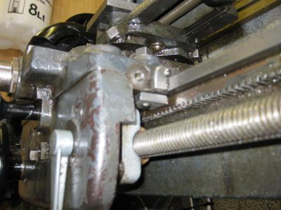
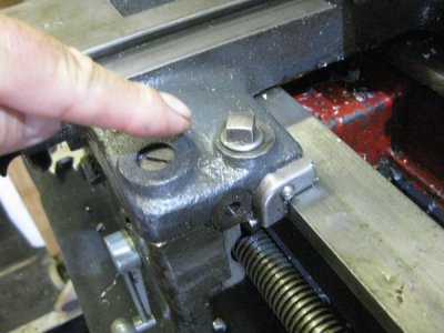
This first picture is me pointing to the carriage lock , you screw it C/W to pull the plate up to the carriage edge and also up against the underside of the bed way . The bearing surfaces that cause the lock are worn after only 72 or so years of use .

The thread indicator has ben removed as it is nigh on useless .. cutting another 16 tooth gear manually on the lathe is going to be one of the next exercises after I finish the current four lathe jobs I have in hand . Luckily I have 36 tooth and a 64 tooth screw cutting gears so accurately indexing the root of the tooth will not be a problem (hopefully ) .
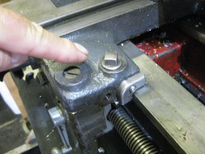
20141001lathe008_zps34c5a4ef.jpg


This picture shows the underside view as best as I could
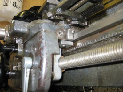
20141001lathe034_zps6b80e4c0.jpg

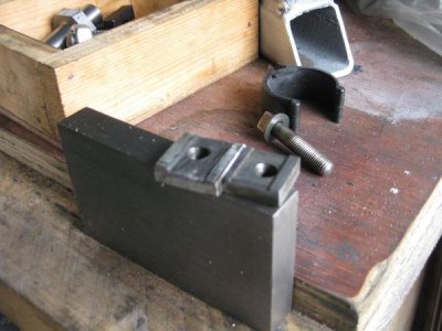
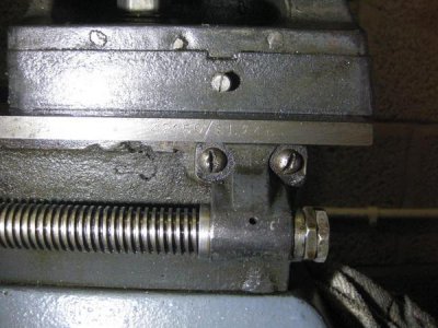
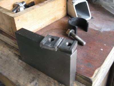
Here is a quick fix made locking plate that I have made ( Note the Rough Engineering Made Easy finish by an Ex REME guy ) and the original better finished one on the right , notice that mine is quite a bit bigger than the original one.

20141001lathe033_zps3784b626.jpg


20141001lathe032_zps90da8741.jpg

The screw thread hole was put to one side like the original ... though I've since found that there is no real need to do this .
When I make the MK 2 version it will be more centrally placed as well as my making the plate even bigger by about a 1/10 of an inch in length and 1/16 in width . I can't make it any thicker for the 6 mm plate is about as thick as it can go before it fouls on the cast metal of the carriage that houses the half nut followers

Now a quick peep at some data marks & an info plate

The brass end plate is the one that shows the original General Electric Company motor, made in England to the electrical regulations of 1924
20141001lathe024_zps1ff2fd13.jpg

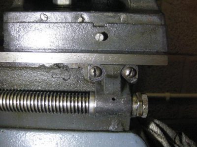
This is the bed stamping on the front face of the RH end of the bed showing the serial number .
Does this first set " 42150 " tie in with the Atlas or Craftsman lathes ?
Does SL 346 part of the serial number indicate that it is Sphere Lathe number 346 ?
20141001lathe019_zpsc3ce87f3.jpg


The headstock foot of the lathe carries the cast in impression for Sphere . Judging by the colour of the paint someone has re painted the feet & lower front of the bed as the back f the lathe is a typical very old dark grey that was so typical of British Military engineering machinery of the period .

20141001lathe025_zpscdfdf57a.jpg


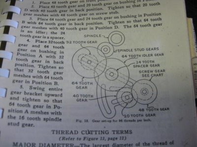
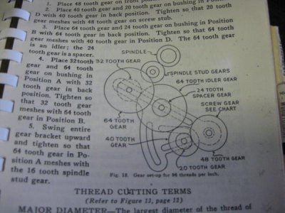
I decided to get adventurous & build this gear train of 96 tpi for I want to set up so I can auto cut about 18 feet of aluminium, bar nice and gently as I got fed up turning the fed screw and having to reposition & lock the carriage every two inches of travel .
the only problem is that I have to make the bearing and mounting bolt for one of the sets of gears as there are only two that came with the lathe and this train needs three. I've made part of it today ( the mounting sleeve/ top hat , but will sleep on how to solve the mounting bolt exercise using materials I have to hand .
20141001lathe002_zps5503f2ec.jpg

20141001lathe008_zps34c5a4ef.jpg

20141001lathe034_zps6b80e4c0.jpg

20141001lathe033_zps3784b626.jpg

20141001lathe032_zps90da8741.jpg

20141001lathe024_zps1ff2fd13.jpg

20141001lathe019_zpsc3ce87f3.jpg

20141001lathe025_zpscdfdf57a.jpg

20141001lathe002_zps5503f2ec.jpg
 
Last edited:
I don't know the answers to either question. The Atlas 10" and 12" lathes with stamped (as opposed to being on the nameplate) serial numbers were stamped on top of the bed, at the right end of the front way, in the area not run over by either the tailstock or the carriage. However, "42150" could be numbers out of the Atlas pool as TH54 041325 was reported to have spindle bearings engraved 1/2/1943 (January 02, 1943). SL 346 could also logically be Sphere Lathe #346, although many Atlas and some Craftsman beds have an S stamped to the right of the serial number.

I'll try to remember to look at the carriage lock plate on my 3996 tomorrow. Forgot to do it this afternoon.

This is the bed stamping on the front face of the RH end of the bed showing the serial number .
Does this first set " 42150 " tie in with the Atlas or Craftsman lathes ?
Does SL 346 part of the serial number indicate that it is Sphere Lathe number 346 ?

20141001lathe019_zpsc3ce87f3.jpg

20141001lathe019_zpsc3ce87f3.jpg
 
Back
Top