Hi guys, the weather has been crappy lately so decided it was a good time to finish off a project I had in mind for quite a while. So I decided to build a battery charger using a rewound microwave oven transformer. I had rewound this one before to make a spot welder but decided that it wasn't going to be big enough so I rewound a 140A arc welder for that purpose, so this left me this transformer as a spare.
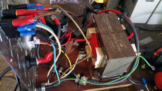
I had originally wound it with 70mm square cable for the welder, followed by 10mm square multi-strand cable for the charger but unfortunately the insulation was fairly thick on that cable and so I couldn't fit enough wraps in to get the desired voltage required. So unwound the secondary and replaced it with 8BS auto multi-strand cable which gave me the desired amount of coils around the core. Although I did have to experiment a bit to get the right amount of wraps. One or two wraps too many and the resultant end voltage, ended up being too high for normal lead acid and AGM batteries. So now I think I have found the sweet spot in that on an AGM battery the voltage ends up at about 14.3 volts and on the plain lead acid type it ends up at about 14.01V. At least that is when I disconnect it from charging.
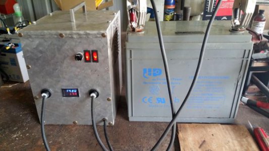
At that stage the batteries are getting about 1.5a to 1.8a The AGM battery shown in the last pic is a 150A deep cycle battery which started off with about 10A input and tapered off fairly quickly to about the 1.5A within 15 minutes, it wasn't totally discharged and it still had a fair charge before I started re-charging it.
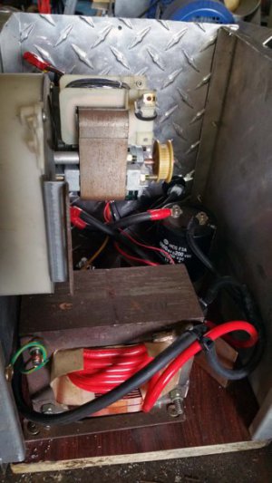
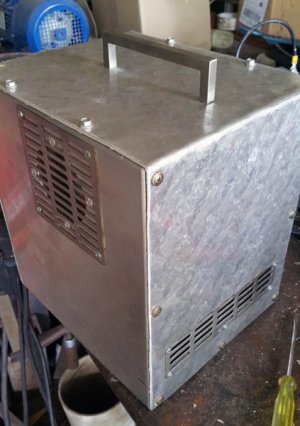
Now to the build, found some aluminium sheets in the shed and cut them down to size, a mixture of tread plate and plain sheets, had to make some folds on it so clamped it down to the work bench with a piece of triangular 10mm plate and a big G clamp, knocked the folds to shape with a hammer. Slit and flattened some 40mm copper pipe to make the heat shield for the 150amp full bridge rectifier. Bit of Silver CPU heat paste between the two to dissipate the heat better. Screwed the lot down to a piece of chipboard, still want to build some feet for it.
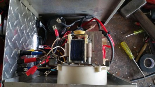
Connected the DC output to a 240V? 6800uF capacitor on the DC side which boosted the voltage and to reduce the inevitable ripple, but not sure by how much as I don't own an oscilloscope, then connected the DC output to a shunt and on to a amp/voltage gauge via the shunt. A 10A fuse protects the lot ( will change it to a 5a fuse when I get one) and it has 2 switches, one for the input transformer power and the second to the fan so I can leave the fan running to cool the everything inside after the transformer is switched off.
I found an old fan in my scrap pile so fitted it to suck air in and blow air onto the transformer, the air then diverts around to the rectifier, then the air gets pushed out the back on the bottom. Having said that the fan is a bit noisy so some time down the track I may replace it with something quieter.(although currently the noise reminds me that the fan is still running) The stainless steel air grate strips come from our old kitchen range hood.
This charger is more of a power supply than anything else but it will be good as a quick charger for a discharged large battery, my current charger would take up to 24-30 hours to charge this battery up. So I am hoping to do a quick charge and then swap it to the second charger which is a multi stage 8 amp one to finish it off.
I am not sure what this transformer will output so will have to watch that it doesn't put out too many amps and also the battery temp if the battery charge is very low, but so far so good. The first charger I made was a 4amp one about 50 years ago in Tech school, so it was satisfying to go back to basics and dig up old school memories.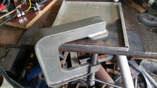


