Jim,
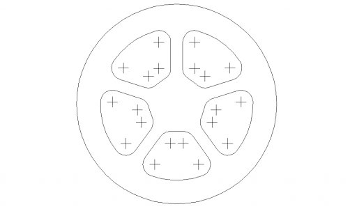
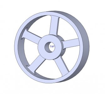
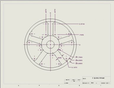
This is actually fairly simple with a rotary table. The angles between spokes are 72 degrees. Zero your DRO x and y at the center of the RT. You will only need locate the coordinates of one set the crosses as indicate in Gene's drawing. The spokes will be made by movement in one axis only. If you choose the y axis, find the coordinates for the crosses on either side of the vertical spoke. The x values will be the same for all four except of sign. The two sets of y values will be the same y within a pair. Offset the x coordinate by the appropriate amount (half the thickness of the spoke plus tool diameter). Begin your cut at the first y coordinate and move to the second. Do not touch the x coordinate at this time. When that side is finished, move to the other side of the spoke and repeat to complete the spoke. To machine the remaining spokes, rotate the table 72, 144, 216, 288 degrees and repeat the process. The x and y moves are the same for each.
To machine the flange, leave the x and y coordinate as is. If you finished on the outside, you can machine the inside of the flange. You will be using the rotary table to do the machining. And you are at the start point. You can rotate the table until you are almost intersecting the machined slot. You now have several options. 1. You can eyeball the final movement to just come short of kissing the second spoke. 2. You can move the x coordinate to the opposite side of the spoke (the minus value) and machine in the opposite direction. 3. You can calculate what the endpoint angle would be and rotate to angle. Option 1 is the easiest. Use Option 2 for precision.
If you need assistance with determining the coordinate values, I can set this up fairly easily in CAD. I would just need your dimensions (hub diameter spoke width, flange inner diameter, flange outer diameter).
Bob


