- Joined
- May 31, 2019
- Messages
- 2
Hi guys,
I'm fairly new here so please forgive me in advance if I break any rules unintentionally.
I recently acquired an old 1970 Bridgeport 1J mill after our 1930s Rouchard finally died. It was fitted with the original Bridgeport geared power feed unit which was temperamental and has now died (motor finally failed) so I bought a new modern power feed unit to retrofit. The mill has been abused in its life but has cleaned up well. I've retrofitted a new 2hp motor as someone had fitted a small single phase 3/4hp foot mount motor at some point in its life which was slightly dodgy, and fitting a VFD to drive the new motor. Anyway, back to my reason for posting.
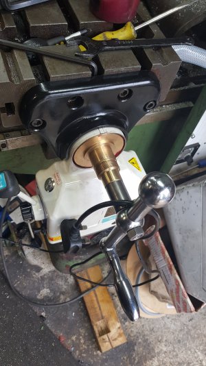
I did a little surfing on forums and saw that the general consensus was that the leadscrew is short and that there was an extension shaft pinned to the lead screw to drive the old power feed. To retrofit the new modern type power feed you simply needed an adaptor shaft available online to pin to the screw and extend it past the bed & drive the new motor.
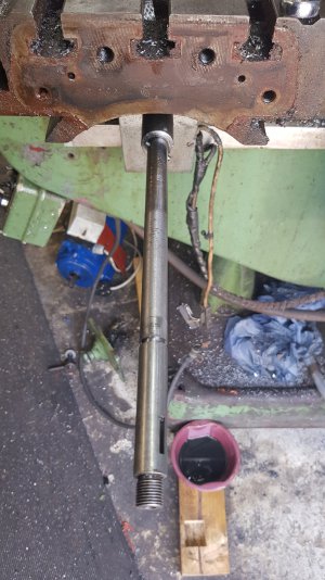
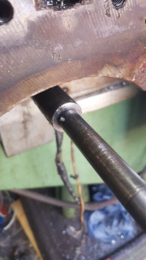
This is where I have come unstuck. After stripping the old power feed I have a 1 piece long shaft with a pin which drives a sleeve which intern was feed by the original geared unit.
Is this a common lead screw? I'm a small single man engineer shop so have the means to turn down the adapter shaft (if I buy one) on my Gate Sturditurn lathe to fit the leadscrew (if I cut it short), but I'm curious if anyone had done a similar mod before? I'd machine an adapter up myself but I don't have the means to machine the key slots to drive the bevel gear as my mill is obviously now in pieces. Any advice or input would be appreciated.


