- Joined
- Sep 22, 2010
- Messages
- 7,222
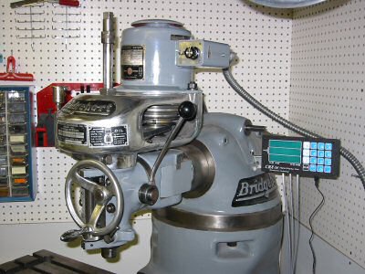
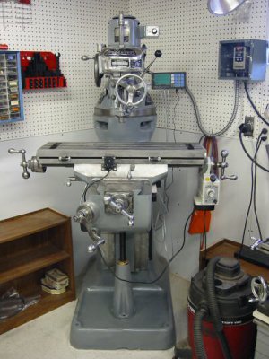
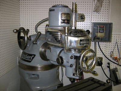
Bridgeport Mill - Rebuild
by Kay Fisher
Errol accepts cash, check, money order and PayPal. He has shipped out about 150 copies and has yet to have anyone ask for a refund.
Latest CD Contents as of 14 Jan 2003
Bridgeport Manuals
1981 Programming Manual
1983 Programming Manual
R2E3 Manual
Series II NC Programming Manual
Student Manual
Bridgeport Series 1 Install, Operate and Maintain
Manual
Quick Change Tooling for the J Head
Brown and Sharpe
No. 3 Mill Manual
Fundamentals of Machine Tools
Grinding and Lapping
1907 Treatise on Grinding and Lapping
Grinding Dressers
J and S Fluidmotion
Optidress Manual
Selecting the Right Grinding Wheel (Norton)
Tangential Wheel Dresser
Jacobs Chuck
Jacobs Rubber Collet Chuck
Leblond 15 and 19 Inch Lathes
Leblond Manual
Machinery Repair
Odds and Ends
Thread Elements Jones and Lamson
Shaper Work
Shapers - Chapter 1 and 2 Machine Tool Operation
Errol Groff
180 Middle Road
Preston, CT 06365 8206
Errol Groff
Instructor, Machine Tool Department
H.H. Ellis Technical School
(860) 774-8511
Home Page:
http://pages.cthome.net/errol.groff/
One source for Bridgeport information is the Yahoo group “Bridgeport_Mill” which you can join at http://groups.yahoo.com/.
Another is Tony Griffiths’ machine tool information website. This site has information about many machines, including lathes and mills. The Bridgeport area includes descriptions of accessories that haven’t been made in years:
www.lathes.co.uk/bridgeport
Serial Numbers
This chart is a cross reference from Bridgeport serial numbers to date of manufacture including an estimate of the number produced each year:
Round Ram
Year Serial Number Range # Made
1938 BH-1 thru BH-39 39
1939 BH-40 thru BH-252 213
1940 BH-253 thru BH-656 404
1941 BH-657 thru BH-1549 893
1942 BH-1550 thru BH-2943 1394
1943 BH-2944 thru BH-4105 1162
1944 BH-4106 thru BH-4997 892
1945 BH-4998 thru BH-5930 933
1946 BH-5931 thru BH-7235 1305
1947 BH-7236 thru BH-8814 1579
1948 BH-8815 thru BH-10381 1567
1949 BH-10382 thru BH-11378 997
1950 BH-11379 thru BH-12750 1372
1951 BH-12751 thru BH-14489 1739
1952 BH-14490 thru BH-16700 2211
1953 BH-16701 thru BH-19367 2667
1954 BH-19368 thru BH-22732 3365
1955 BH-22733 thru BH-26962 4230
Start V Ram
1956 BR-26963 thru BR-31618 4656
1957 BR-31619 thru BR-37278 5660
1958 BR-37279 thru BR-42110 4832
1959 BR-42111 thru BR-46938 4828
1960 BR-46939 thru BR-52598 5660
1961 BR-52599 thru BR-58552 5954
1962 BR-58553 thru BR-64987 6435
1963 BR-64988 thru BR-71981 6994
1964 BR-71982 thru BR-79538 7557
1965 BR-75939 thru BR-88180 8642
1966 BR-88181 thru BR-98089 9909
1967 BR-98090 thru BR-108351 10262
1968 BR-108352 thru BR-118640 10289
1969 BR-118641 thru BR-131778 13138
1970 BR-131779 thru BR-138139 6361
1971 BR-138640 thru BR-143350 5211
1972 BR-143351 thru BR-149294 5944
1973 BR-149295 thru BR-157909 8615
1974 BR-157910 thru BR-167652 9743
1975 BR-167653 thru BR-174083 6431
1976 BR-174084 thru BR-180697 6614
1977 BR-180698 thru BR-188559 7862
1978 BR-188560 thru BR-196987 8428
1979 BR-196988 thru BR-206296 9309
1980 BR-206297 thru BR-216473 10177
1981 BR-216474 thru BR-227523 11050
1982 BR-227524 thru BR-231700 4177
1983 BR-231701 thru BR-235985 4285
1984 BR-235986 thru BR-241350 5365
1985 BR-241351 thru BR-246659 5309
1986 BR-246660 thru BR-248551 1892
1987 BR-248552 thru BR-250531 1980
1988 BR-250532 thru BR-252874 2343
1989 BR-252875 thru BR-255463 2589
1990 BR-255464 thru BR-257888 2425
1991 BR-257889 thru BR-259897 2009
1992 BR-257898 thru BR-262188 2291
1993 BR-262189 thru BR-264586 2398
1994 BR-264587 thru BR-267635 3049
1995 BR-267636 thru
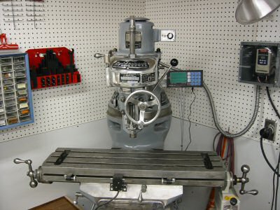
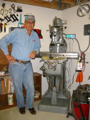
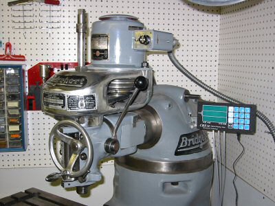
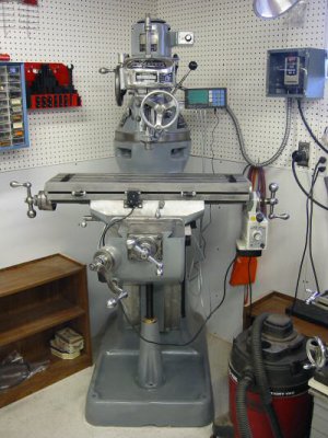
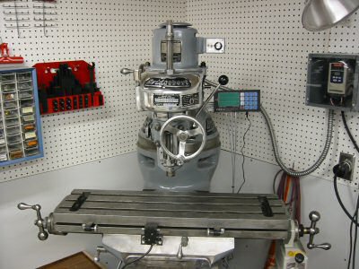
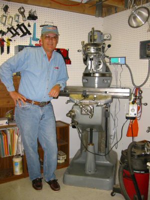
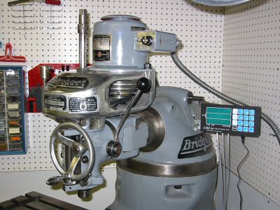
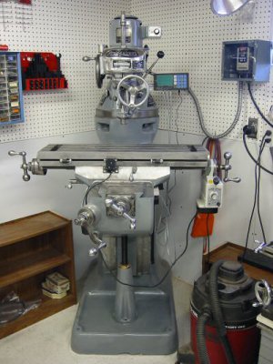
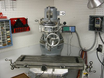
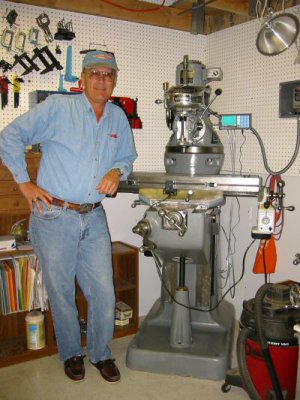
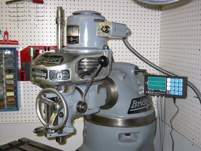
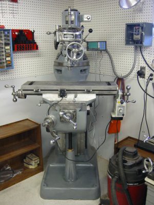
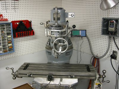
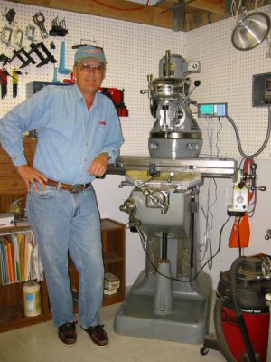
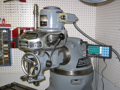
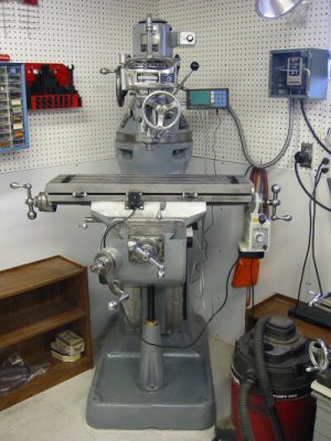
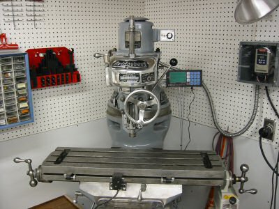
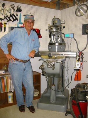
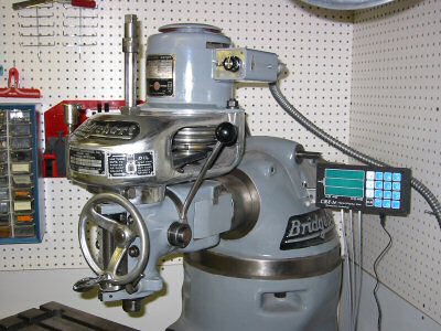
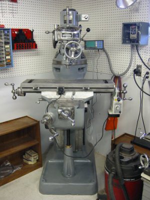
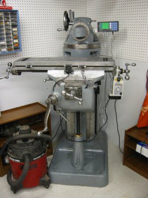
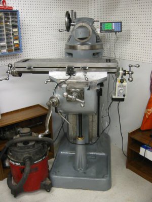
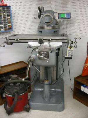
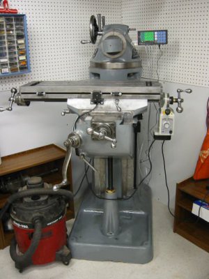
The main serial number, shown in the above chart, is located on the top of the knee in the front. Mine is #7365, which did not include the “BH” prefix. To expose the serial number, crank the saddle back towards the column until the chip guard plate slides back an inch. My Bridgeport was manufactured in 1947 – the same year I was born.
The door contains the full serial number BH7365, which matches the knee. It also has a patent number 2275291, which matches one on the table. The Saddle has a serial number on the left side next to the table lock handle. It should match the table serial number. Mine is #527. I don’t remember where the table serial number is. I suspect it is under the left or right bearing bracket. It really doesn’t matter as it was used during assembly at the factory to insure the surfaces that were hand scraped match up on the same machine. The table also has a patent number on the front center. Mine is #2275291. If anybody knows for sure where the table serial number is please let me know and I’ll update this paragraph.
Each dial and handle is stamped with an A, B, C, or D. The left handle and dial are A. There is also an A on the front left of the table. The right handle and dial are B. There is a B on the front right to match. The cross feed (Y axis) handle and dial are C. The elevating (Z axis) dial is D. They are machined to match and won’t fit as well anywhere else.
The M-Head serial number is on the left of the quill housing. Mine is #M21472. It should match the serial number on the belt housing.
The belt-housing serial number is on a label fastened to the front of the housing. Mine is #M21472. It should match the M-head serial number.
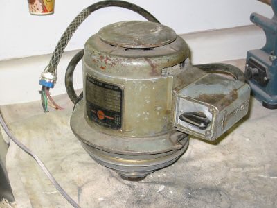
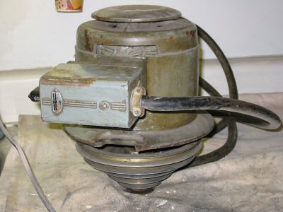
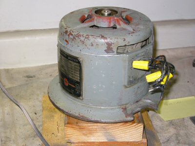
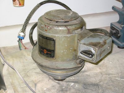
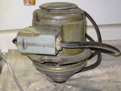
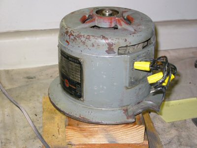
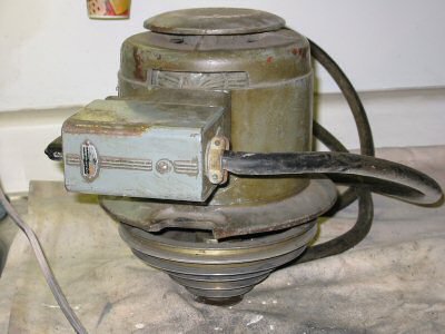
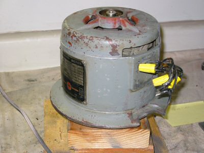
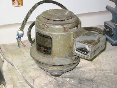
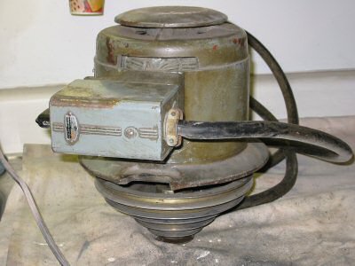
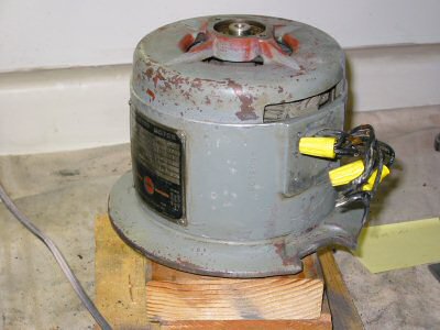
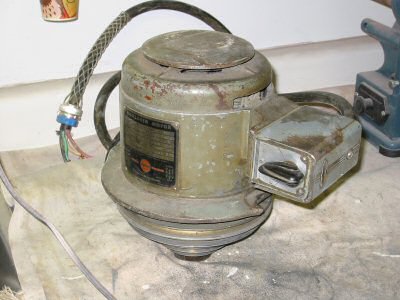
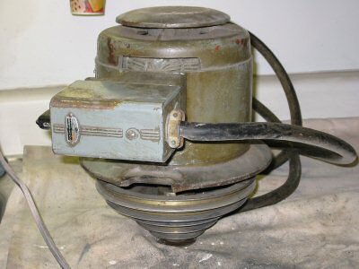
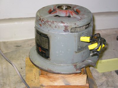
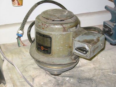
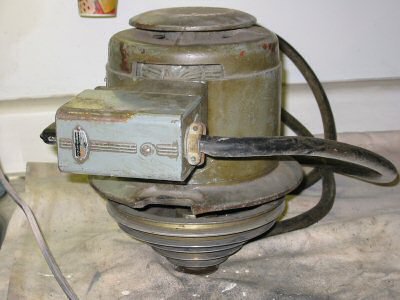
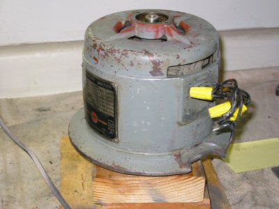
Not all motors have serial numbers. They changed type and manufacturers of motors over the years. Mine has a serial number on a label on the front of the motor. It is #3064.
http://www.hqtinc.com
They have an excellent catalog. You have to order from “High Quality Tools” through a distributor. I have ordered through:
Spare Parts
Spare parts for Bridgeport mills are available from many places. My favorite for new parts is High Quality Tools.
They have an excellent catalog. You have to order from “High Quality Tools” through a distributor. I have ordered through:
There are always parts for Bridgeport mills for sale on eBay:
www.ebay.com
Select the category “Business & Industrial” then select the sub category “metalworking”. Then search for “Bridgeport”.
http://www.hqtinc.com
They have an excellent catalog that has a small diagram of the lube system available from Lube USA. You have to order from “High Quality Tools” through a distributor. I have ordered through:
Here is the part list of the items that I bought from Lube USA.
Qty
Part #
Item Description
Price Each
1
185052
HTG-0 Flow Adapter
$13.09
1
185002
HAS-0 Flow Unit
$7.29
1
186101
Elbow Connector
$2.94
11
106271
Tubing Insert 4mm
$0.41
13
106254
Compression Sleeve 4mm
$0.31
7
186252
Compression Bushing
$0.70
6
186251
Compression Nut
$0.70
4
106901
Tube Ends Elbow, Drive 3mm
$3.77
10ft
106801
4mm Nylon Tubing, Natural
$0.50
1
185009
HJB-0 Flow Unit
$7.29
4
185010
HJB-1 Flow Unit
$7.29
1
186404
PJ-7S Junction
$13.09
1
106707
12" Flexible Hose 300mm
$13.99
1
186420
PJ-3 Junction
$4.14
2
186255
Closure Plug
$0.69
UPS shipping
$8.58
Total
$138.67
The part numbers that start with 106 are metric. The part numbers that start with 185 and 186 are English. The output from the Bijur lubricator is 1/8” NPT as are the Bridgeport zerk oilers.
The list above is correct to the best of my knowledge. Originally I was a couple of items short and had to pay additional shipping cost for a couple of small parts. I advise anyone ordering to order extra compression sleeves, tubing, and drive barbs to allow for mistakes
Measuring and Layout
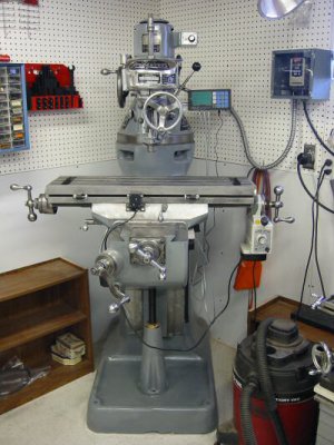
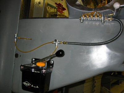
The new Bridgeports have 12 inches of Y travel where mine has 9 inches of travel. I measured a new Bridgeport mill and the lubricator was approximately 10.25” down from the top of the knee to the top of the lubricator and 4.5” from the back of the knee to the back of the lubricator.
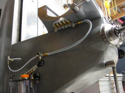
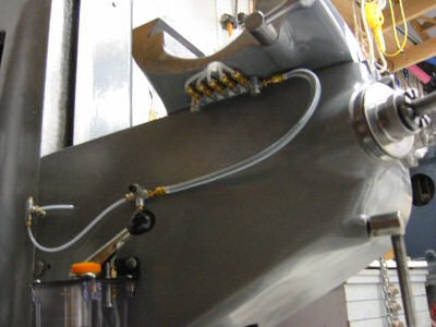
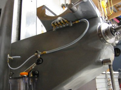
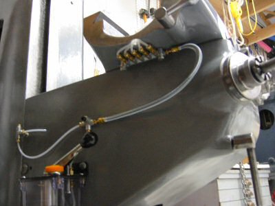
Because my knee is smaller I placed my lubricator 7.25” down from the top of the knee and 4.25” from the back. I mounted all my hardware on the mill by drilling and tapping ¼x20 holes.
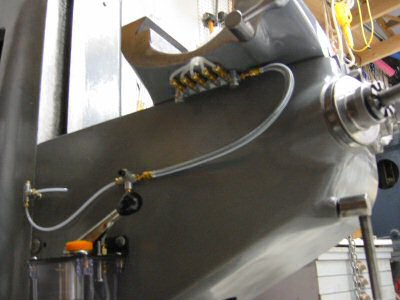
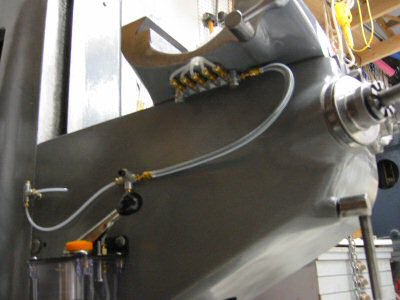
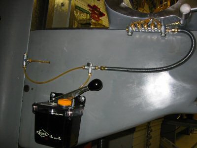
Lube System and Junction
Photo by Kay Fisher
I also measured and stared at the flexible hose for quite a long time before I decided that I did not need the 14” flexible hose and instead ordered a 12” hose.
I also got a good diagram for a 9 point lubrication system from
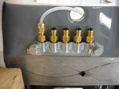
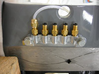
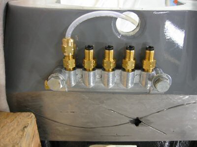
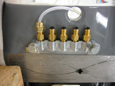
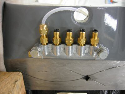
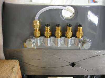
5 Port Junction on Saddle
Photo by Kay Fisher
The junction should be located as close to the knee ways as possible because the tubing must make a sharp bend through the new drilled and reamed ¾ inch hole into the top of the saddle. I wish I had positioned mine about ¼” closer to the saddle.
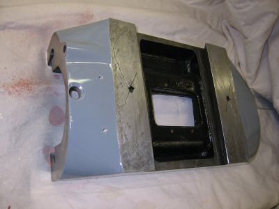
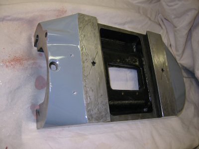
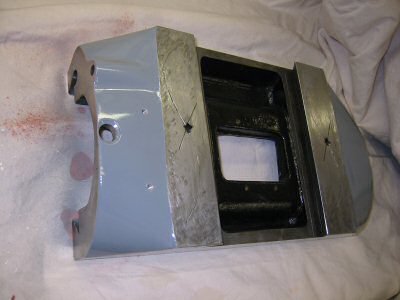
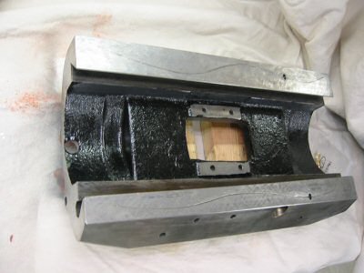
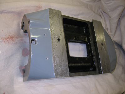
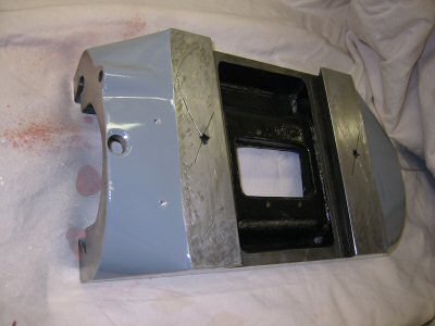
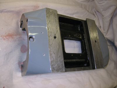
Saddle With Holes Drilled
Photo by Kay Fisher
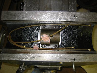
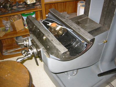
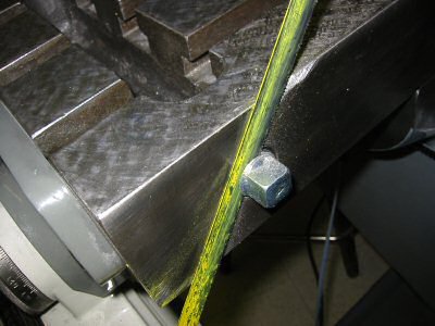
Instead of running the lines to the old zerk holes, I cross-drilled into the existing oil paths and installed (hammered in) drive barbs (elbow connectors) as per Michael Morgan’s suggestion. To make sure I didn’t miss the existing oil passageways, I inserted brass rods through the old zerk holes and made sure that my measurements agreed with my line of site observations.
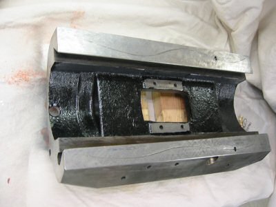
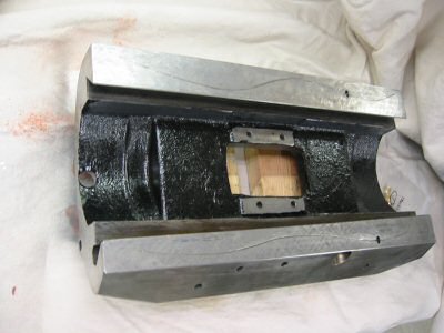
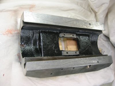
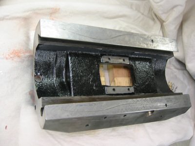
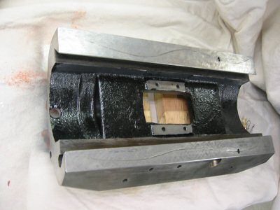
View of Saddle for Drilling
Photo by Kay Fisher
I asked on the phone what size hole to drill for the drive barbs. The Lube USA fellow said 1/8”. This is correct for the barb but I drilled a couple sizes smaller and worked my way out to 1/8”.
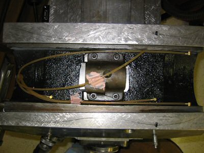
View of Saddle Plumbing
Photo by Kay Fisher
To drill in the sides of the saddle I had to use a 90 degree drill adapter and screw machine (stubby) drill bits. I just barely had room. If you don’t have a screw machine drill bit you can easily just grind off the end of a cheap bit and make one.
One of my critical holes ended up just a bit little too large. I could have ordered the next size larger barb but instead I put a layer of solder on the old one and then it fit tightly.
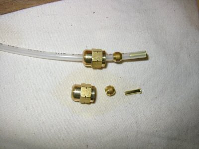
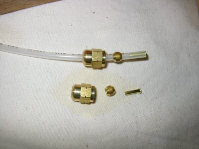
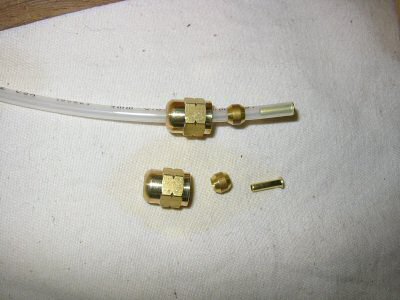
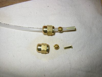
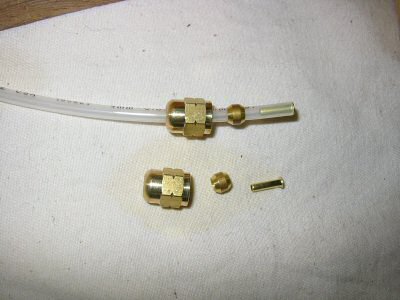
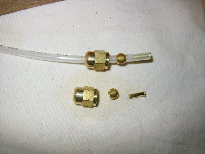
5/32" Tubing and Fittings
Photo by Kay Fisher
The photo above shows the 5/32” tubing with a compression nut, 4mm tubing insert and 4mm compression sleeve.
Meters
I ended up using three #0 meters and the rest #1. A #1 meter puts out twice as much oil as a #0. I put the small #0 meters on the vertical ways and on the cross feed acme screw. Now the cross feed screw gets about 7 drops of oil per cycle. The vertical ways create the biggest mess so I am glad I took Michael Morgan’s advice and put #0 meters on them. I think since they are not under pressure from the weight of the table and because the knee moves less frequently they require less oil.
Feed Nut Lubrication
To get oil into the feed screws there is a hole on top of the feed nut bracket. Normally you center the table (with a mark on the saddle), remove a set-screw in the middle of the table and drip some oil through the hole.
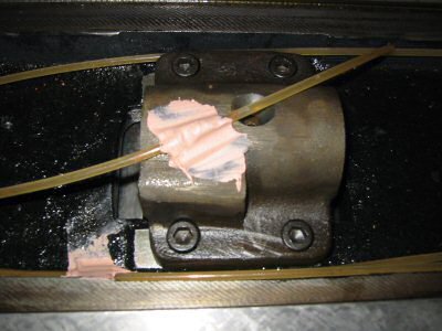
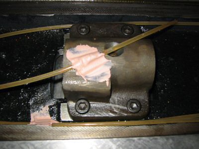
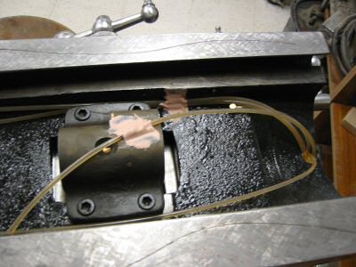
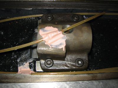
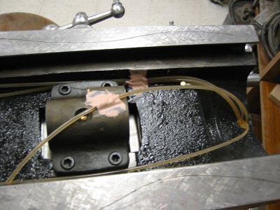
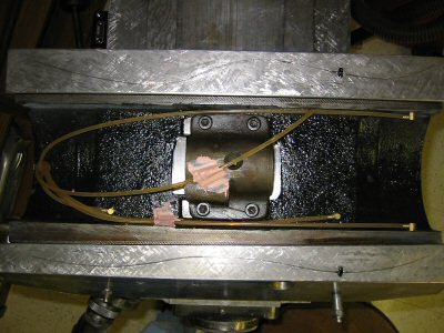
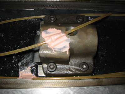
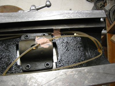
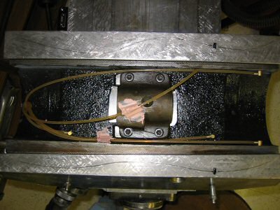
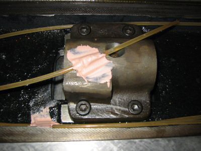
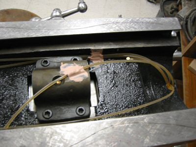
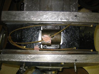
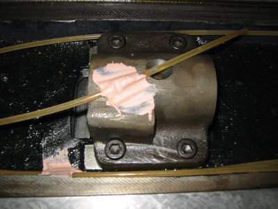
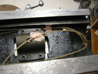
Feed Nut Bracket With Bondo
Photo by Kay Fisher
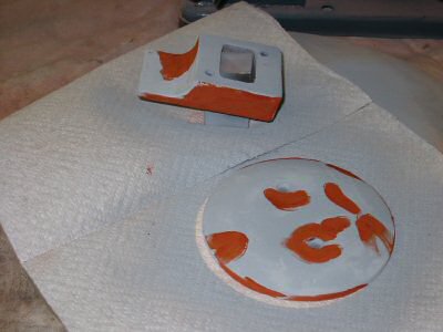
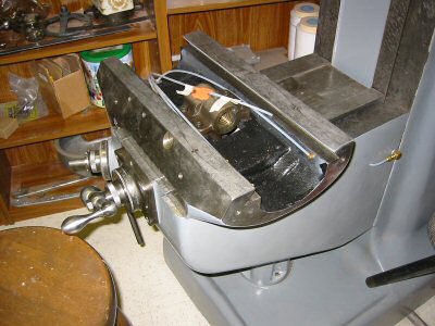
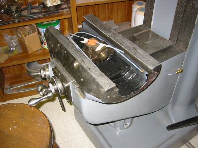
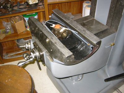
I used bondo to fasten the 5/32 inch nylon tubing to the top of the feed nut bracket. Bondo was my second method of fastening. My first was not successful.
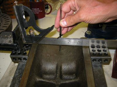
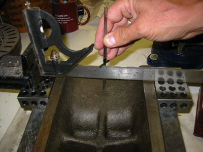
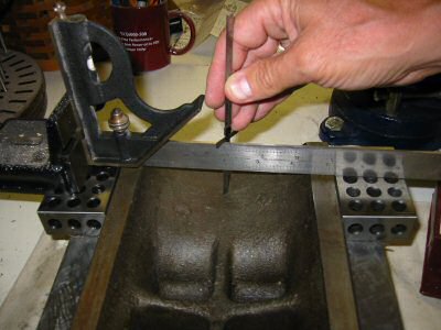
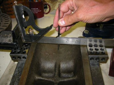
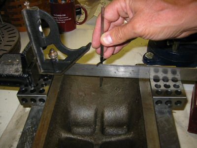
Measuring for Feed Nut Oil
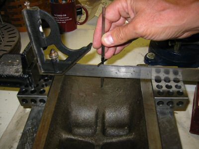
Photo by Kay Fisher
After I fastened the tubing to the bracket I got to thinking it might not clear the bottom of the table. In the photo above I set up some 1 2 3 blocks and measured the depth across the entire bottom of the table. It was just a hair more than 5/32”. In hind site I should have ground a groove in the feed nut bracket with a Dremel tool and laid the tubing in it to have more free space.
Modifications
In my case I elected to modify the original parts list from Lube USA “9 point lubrication system” for three reasons.
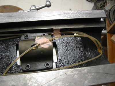
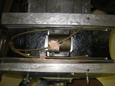
Bondo Two Lube Lines
Photo by Kay Fisher
I also used Bondo to fasten two lube lines that wanted to ride up as shown in the above photo.
Next Time
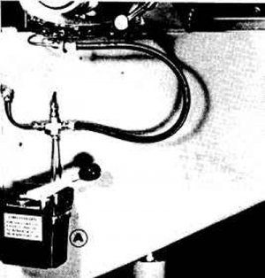
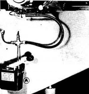
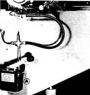
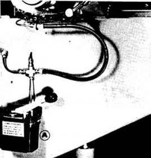
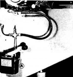
I would do a few things differently if I had to do it again. I would change the layout on the left side of the knee to more closely match the layout pictured in the old Bridgeport manual that comes in Error Groff’s CD “Shaper Work Plus”. The meter on the left side of the saddle sticks out further than the elbow and meter on the right side of the saddle. If I laid out the lines as per the Bridgeport picture I could make the left like the right.
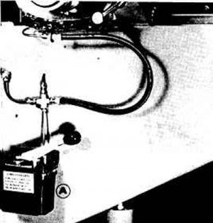
Lubricator Layout
Photo from Bridgeport Manual
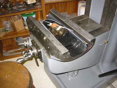
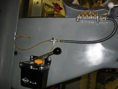
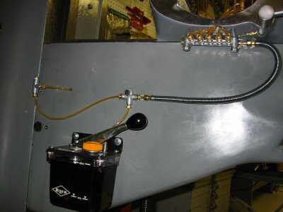
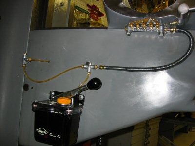
Lube on Right Side of Knee
Photo by Kay Fisher
I would like to have used brass tubing even though it would have been a bit harder to work with.
Way Oil
There has been much discussion on the internet about the proper oil to use. Some have used 30-weight non-detergent motor oil. Some have used chain saw bar oil. I am using “Tru-Edge” brand special way oil 68. I purchased a gallon of it years ago long before I ever had a milling machine. However, the consensus is that the best choice is Mobil Vactra #2 way oil. If I ever run out of my current supply I plan to switch to Mobil Vactra #2. It is ISO grade 68 (SAE-20) and available for $13.82 a gallon as part number 60002151 from:
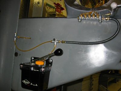
System With Oil in Lines
Photo by Kay Fisher
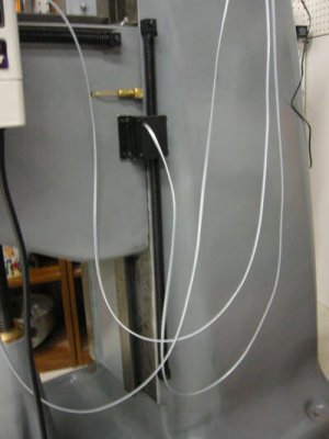
There is an advantage to the nylon tubing. It was very reassuring to see the way lube travel up the clear plastic tubes on all seven of the lines.
Eliminating Zerk Holes
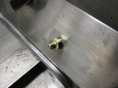
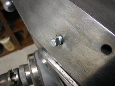
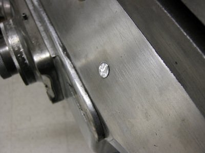
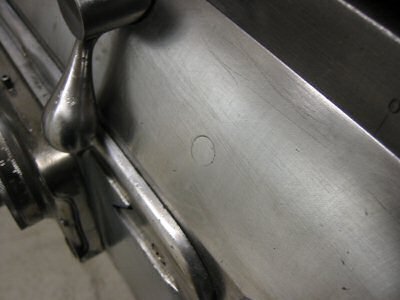
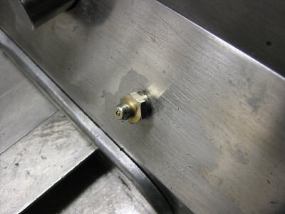
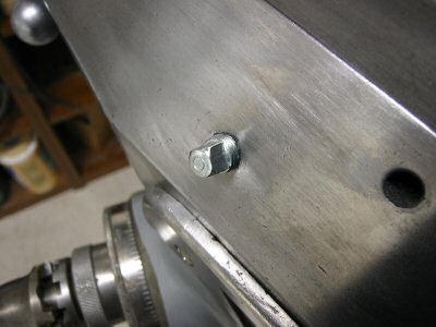
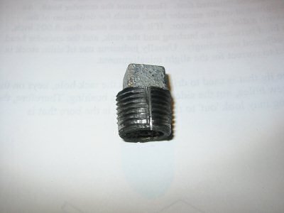
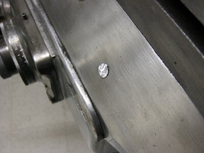
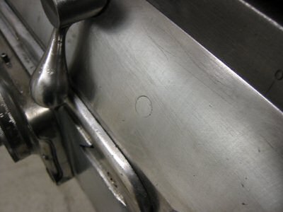
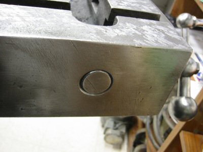
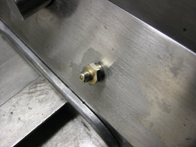
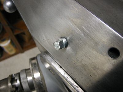
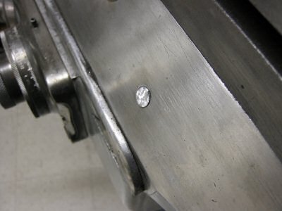
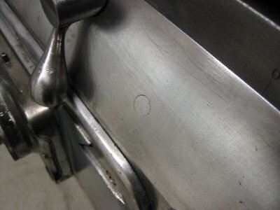
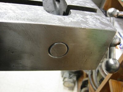
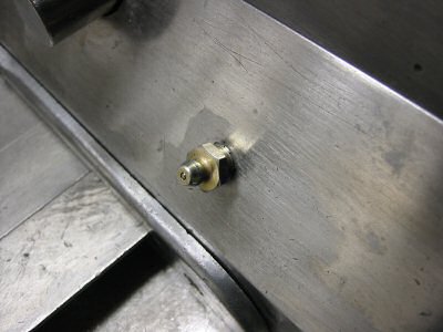
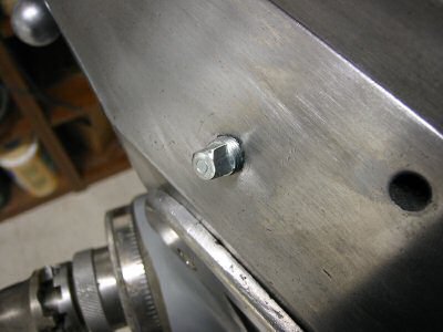
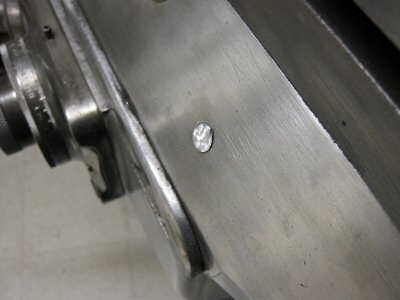
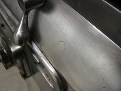
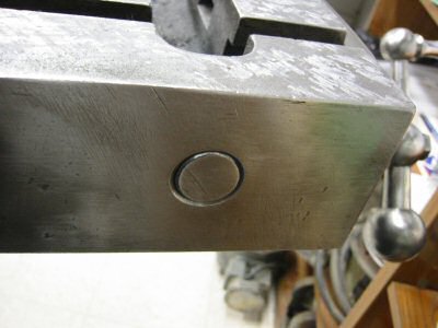
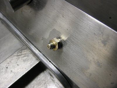
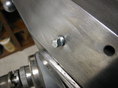
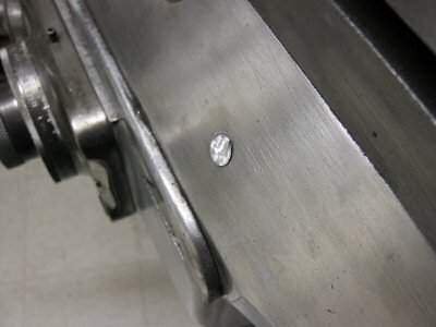
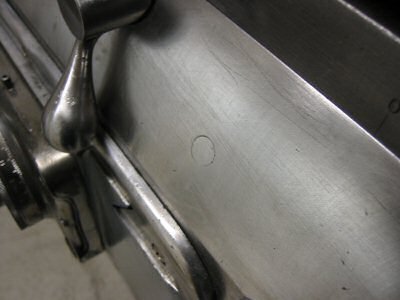
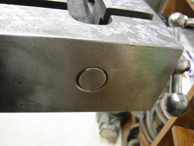
Last but not least – the job isn’t done until the zerk oil holes are plugged. I thought I might want to leave them in as an emergency way of supplying lube. Then I thought I might want to insert plugs made like set screws for easy removal. Finally I decided I just wanted the front to look as nice as possible with little evidence of the previous oil holes. I inserted four 1/8 NPT pipe plugs, ground the heads off with a Dremel wheel, and filed the stub down flush with the saddle.
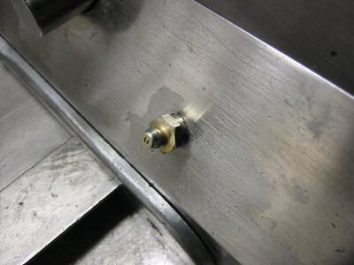
Oil Zerk
Photo by Kay Fisher
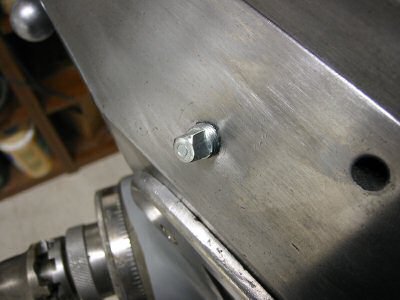
1/8" NPT Plug
Photo by Kay Fisher
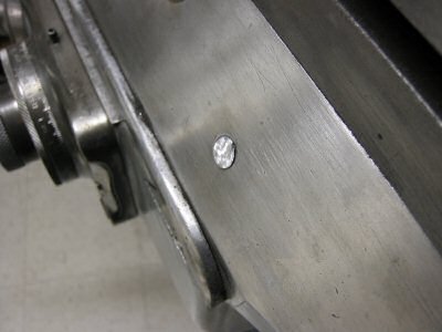
Plug Ground Off by Dremel
Photo by Kay Fisher
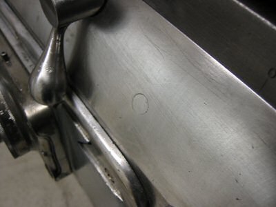
Plug After Filing Down
Photo by Kay Fisher
I am very happy with the one shot lube system. Now it is easy to oil and much more elegant!
www.star-techno.com
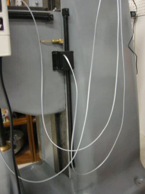
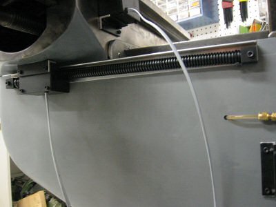
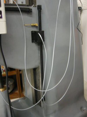
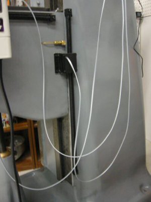
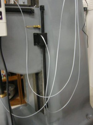
DRO Z Axis
Photo by Kay Fisher
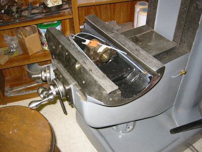
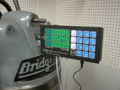
One advantage of the Shooting Star system is that you can cut each scale to the exact length required. By comparison, DROs using glass scales can be cut, but cutting the scale voids the warranty.
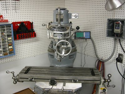
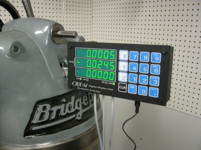
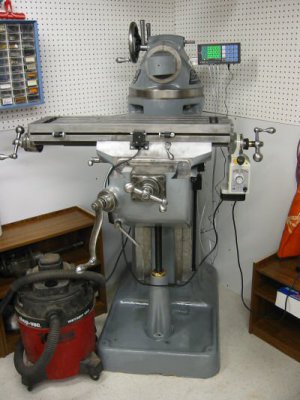
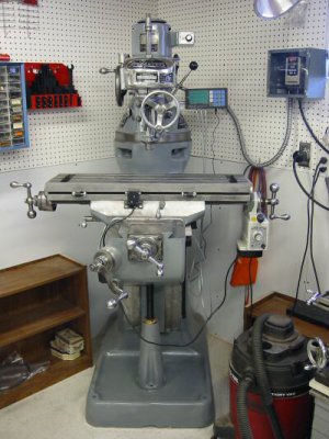
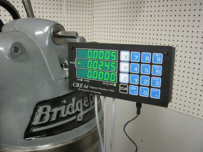
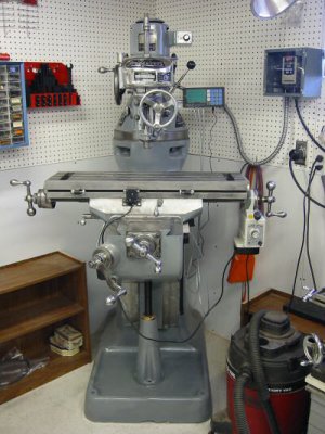
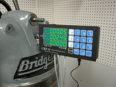
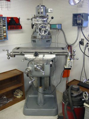
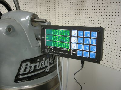
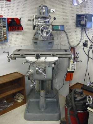
For this machine, I bought a three-axis DRO. Some people put the third axis on the head. I chose to put it on the column. I plan to install a cheap digital indicator on the head later.
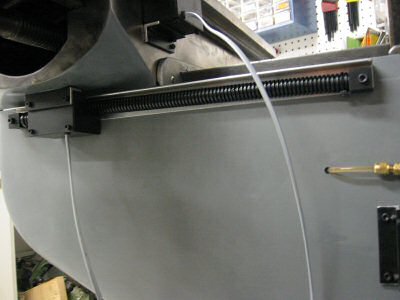
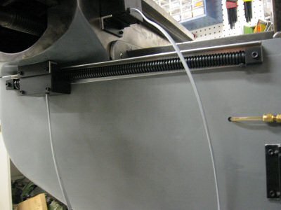
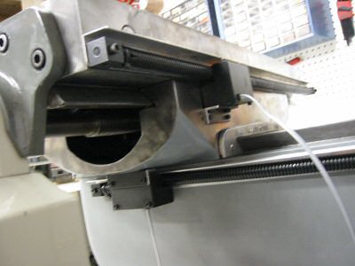
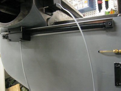
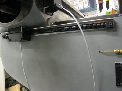
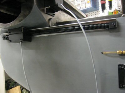
DRO Y Axis
Photo by Kay Fisher
The DRO installation was straightforward and much easier than the installation on my Clausing mill.
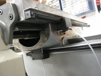
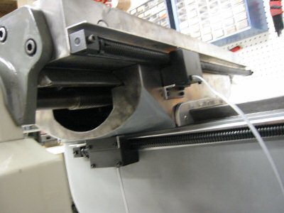
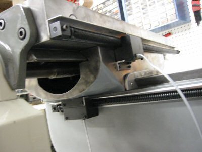
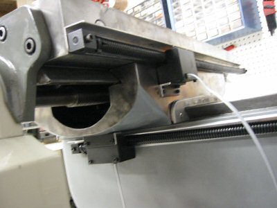
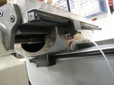
DRO X Axis
Photo by Kay Fisher
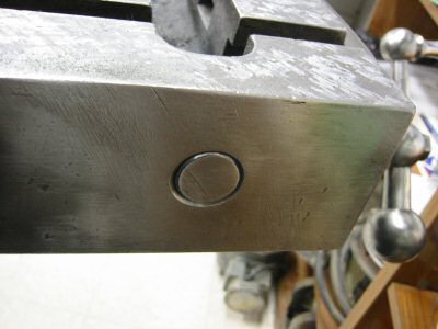
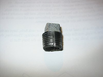
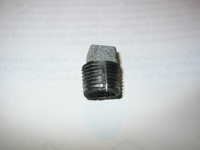
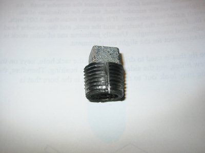
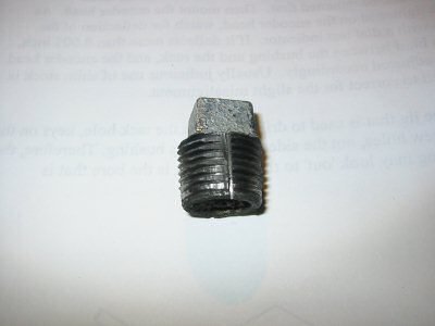
On the backside of the table there were two large coolant system drain holes. I plugged these before installing the X-axis. They were ½ inch NPT so I bought a couple of plugs at the local hardware store. They only went in a couple of turns so I tapped the holes deeper. To avoid the cost of a tap I turned a cheap plug into a tap by grinding a slot in it. I installed the plugs and sawed the ends off. Then I filed the stubs flush to the table.
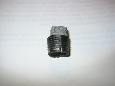
Plumbing Plug Tap
Photo by Kay Fisher
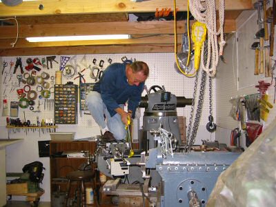
Cutting Head Off Plug
Photo by Kay Fisher
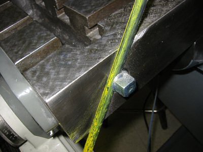
Cutting Head off Plug - Closeup
Photo by Kay Fisher
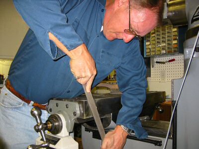
Filing Plug
Photo by Kay Fisher
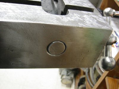
Finished Plug
Photo by Kay Fisher
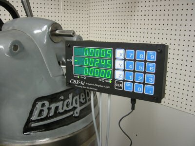
DRO Mounted
Photo by Kay Fisher
www.harborfreight.com
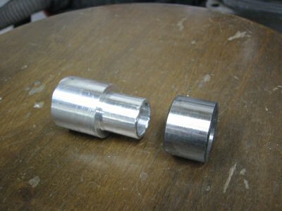
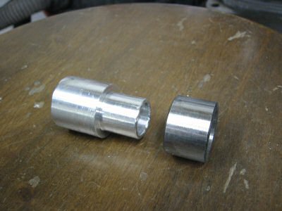
Custom Bushing and Bearing Race
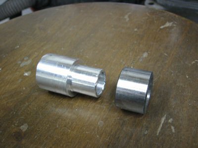
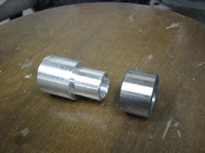
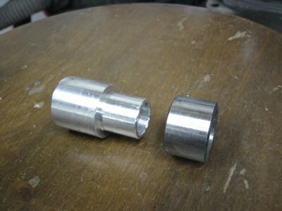
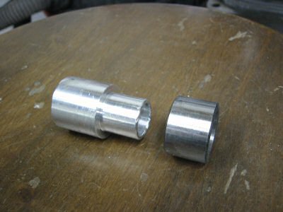
Photo by Kay Fisher
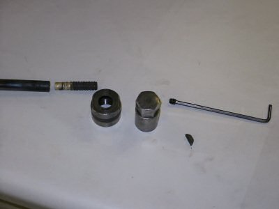
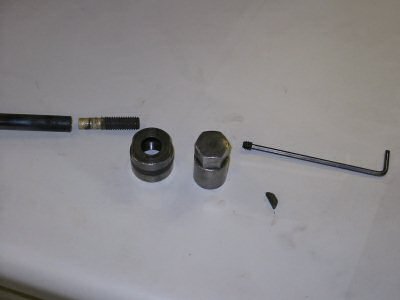
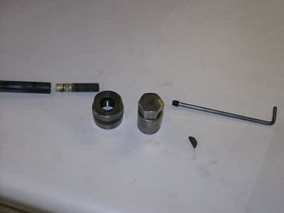
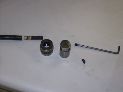
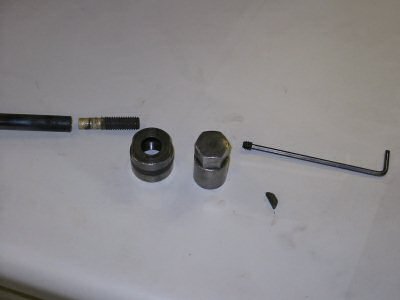
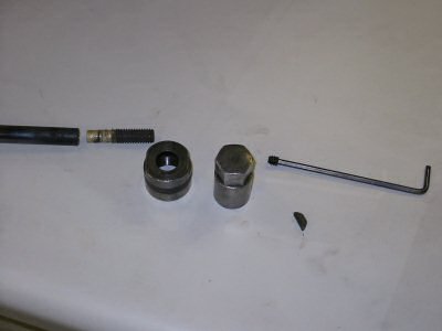
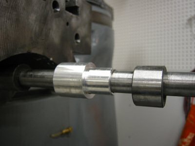
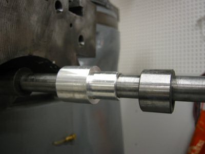
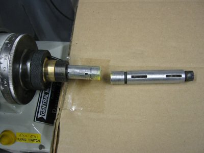
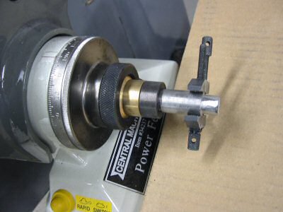
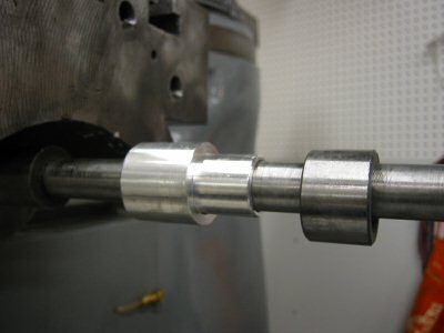
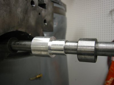
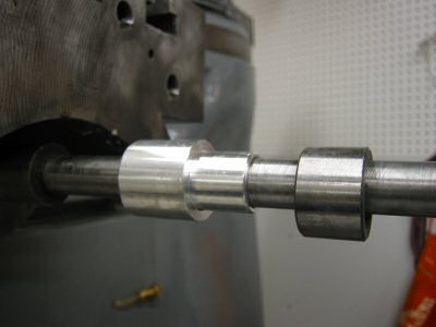
The custom bushing (the left item in the above photo) was the only part I had to manufacture. The item on the right was the bearing race that came with the power drive. The bushing inside diameter is for a sliding fit over the longitudinal feed screw. The large outside diameter was some random scrap diameter. This is only needed to give a shoulder to the smaller end, which is a sliding fit with the supplied bearing race.
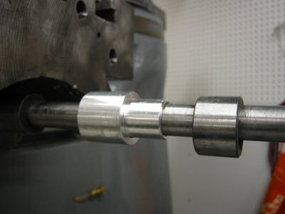
Custom Bushing and Bearing Race on Shaft
Photo by Kay Fisher
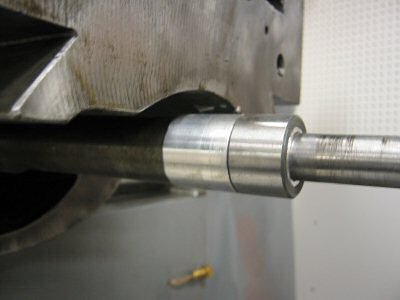
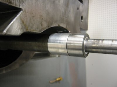
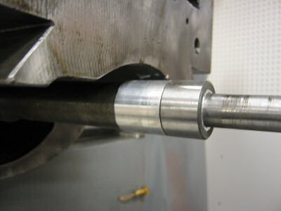
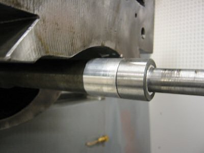
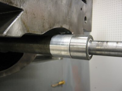
Bushing and Bearing Race Slid Home
Photo by Kay Fisher
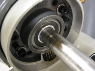
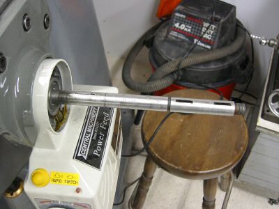
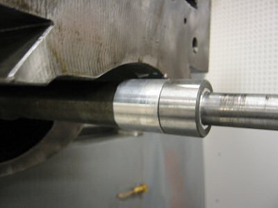
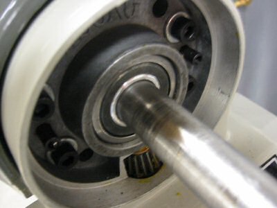
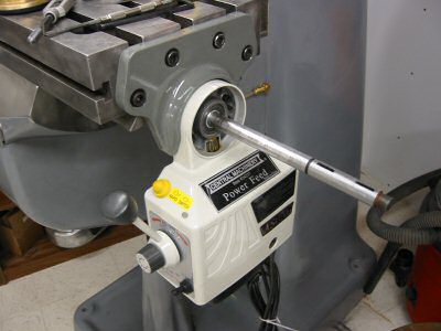
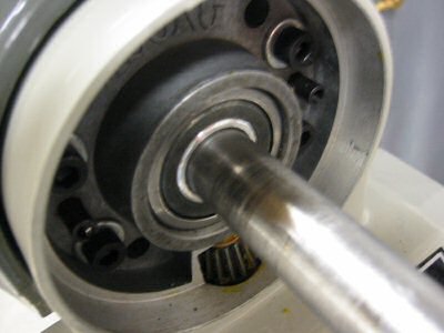
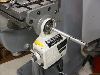
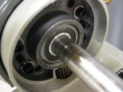
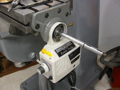
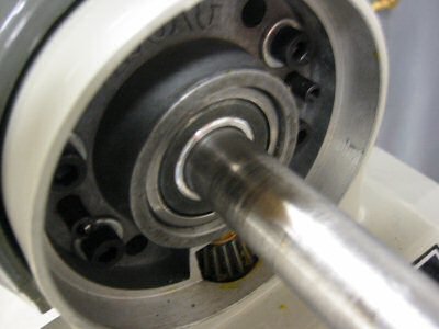
The length of the bushing was such that the end result of the placement of the new bearing race was in line with the end of the roller bearing in the power drive as shown in the next two photos.
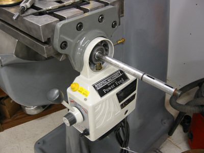
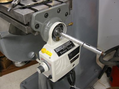
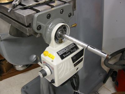
Power Feed Mounted
Photo by Kay Fisher
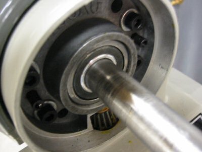
Bearing Aligned with Race
Photo by Kay Fisher
At this point in time I had a mounted power drive but needed to add two keyways like the original shaft except closer in.
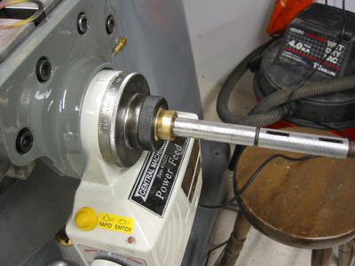
Feed Screw with Dial Installed
Photo by Kay Fisher
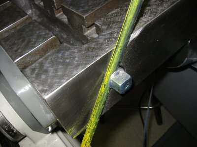
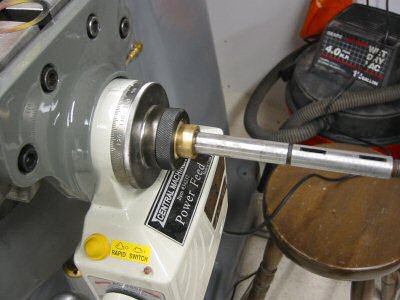
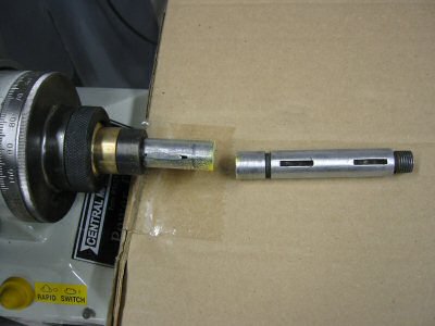
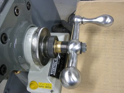
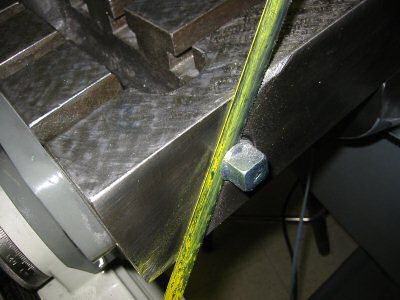
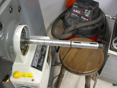
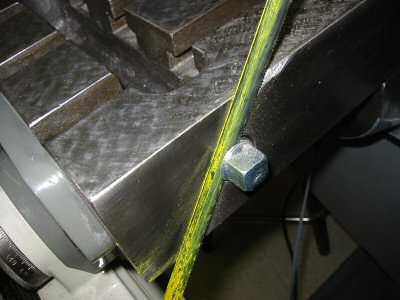
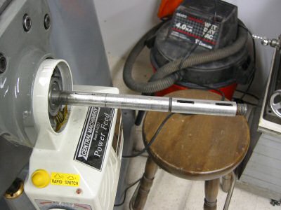
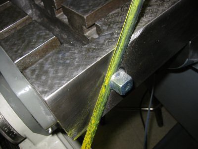
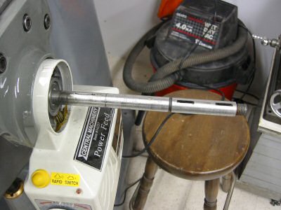
In the photo above I mounted the brass bevel gear, dial, and dial lock nut so that I could make a mark on the shaft with a felt tip pen to determine where I would cut the first keyway.
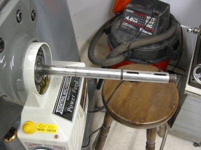
First Keyway (On Left Above Yellow Label)
Photo by Kay Fisher
I cut the keyways with a cutting wheel on a Dremel tool. It was crude but it worked. I would have liked to cut it with my mill but I sold my Clausing and had to get my Bridgeport running before I could do any milling.
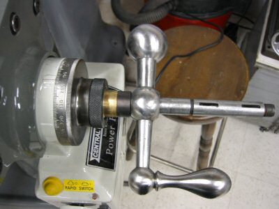
Ball Crank Handle Mounted
Photo by Kay Fisher
Next I mounted the ball crank handle so that I could again mark the location with a felt tip pen and cut the next keyway.
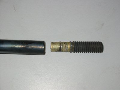
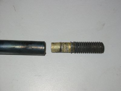
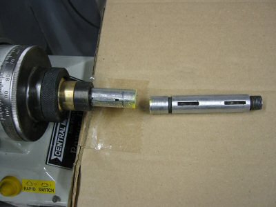
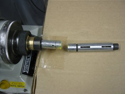
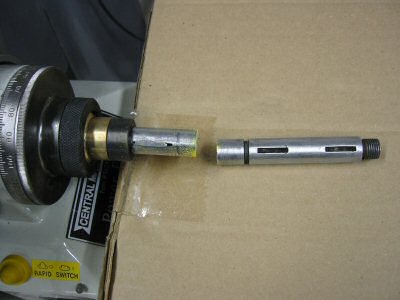
Next comes the moment of truth where I finally cut the end of the feed screw off with my hack saw. There is no turning back now.
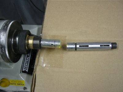
Shortened Feed Screw
Photo by Kay Fisher
If I had a lathe large enough to handle the long feed screw, I would have used it to cut the threads. I didn't, so instead I cut threads the hard way.
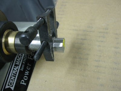
Filing Feed Screw
Photo by Kay Fisher
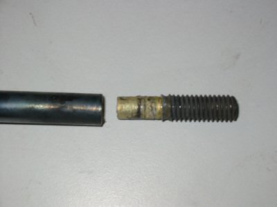
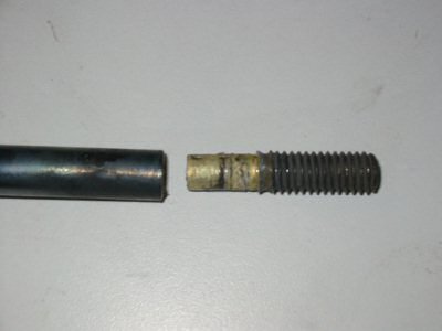
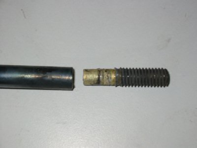
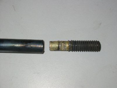
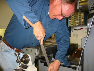
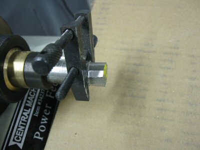
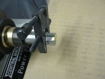
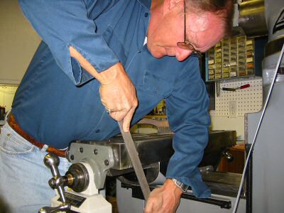
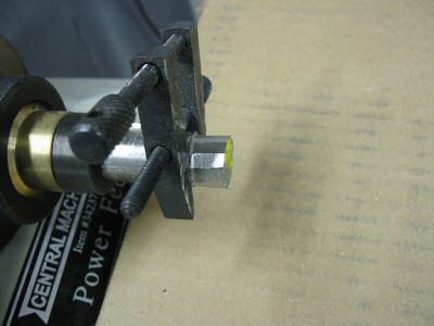
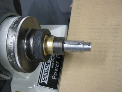
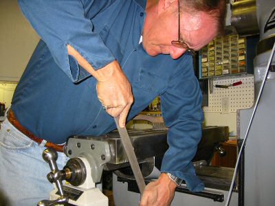
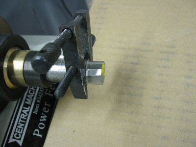
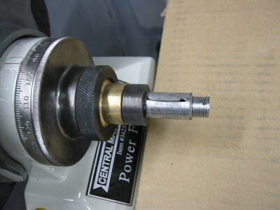
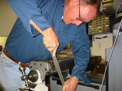
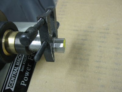
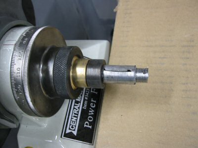
I filed the end of the longitudinal feed screw down by hand until the outside diameter was appropriate for cutting threads for the nut that holds on the ball crank handle. I used a machinist clamp for a file guide. I would take 10 strokes with a file then rotate the handle 40 thousands on the left dial then take another 10 strokes then rotate... All the while I kept checking the diameter with a micrometer As I approached the desired diameter I took less strokes and rotated the handle 20 thousands per filing cycle.
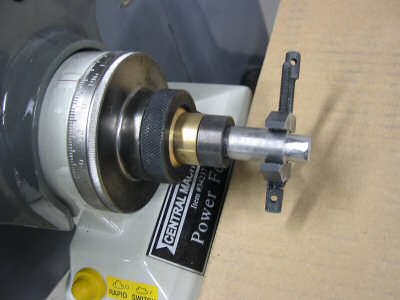
Feed Screw Filed for Threads
Photo by Kay Fisher
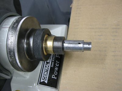
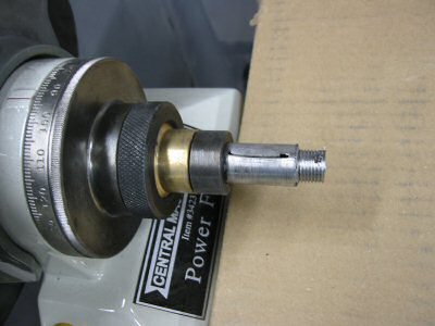
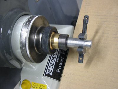
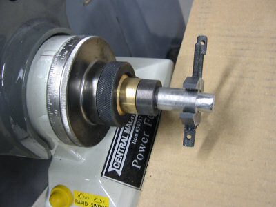
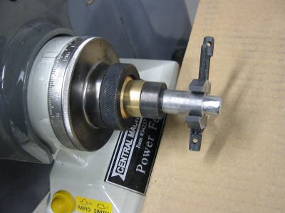
To thread the end I simply used a manual die and was very careful.
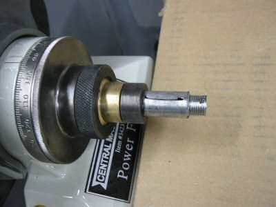
Threading Completed
Photo by Kay Fisher
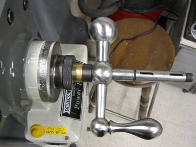
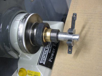
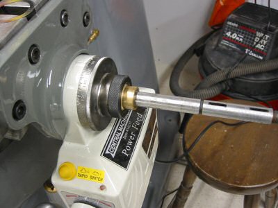
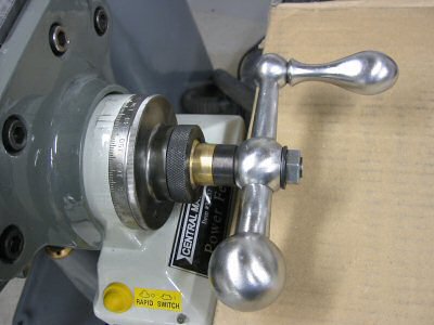
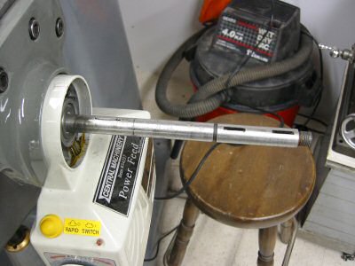
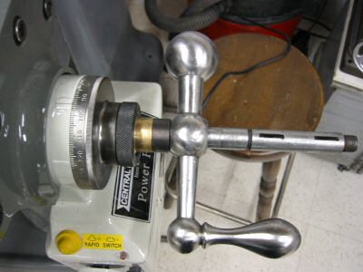
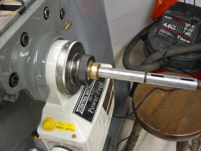
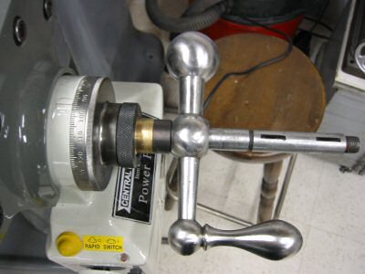
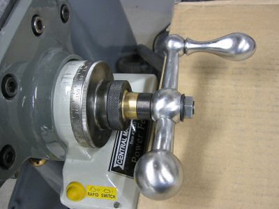
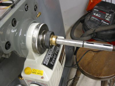
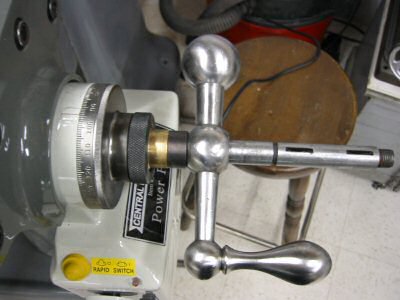
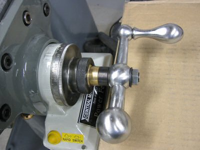
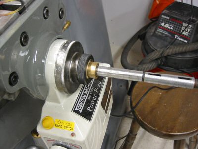
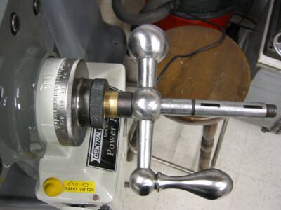
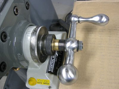
Below is a picture of the completed installation. When you put the nut on the shaft this is the first time you will actually compress the bevel gear against the gear in the power feed assembly. At this time you will have to add the supplied washer/shims as appropriate to get a nice freely moving mechanism. Not enough shims and the handle will take considerable force to turn and the gear will make bad sounds. Too many shims and the gear will feel really loose with too much backlash. This also adjusts the spacing that you see between power feed casting and the indicator dial. Note that the black spacer between the brass bevel gear and the handle is supplied with the power drive kit and is necessary for the handle to clear the power unit below it.
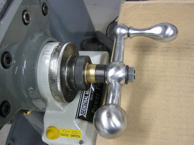
Handle Installed
Photo by Kay Fisher
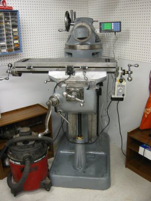
Limit Switches Installed
Photo by Kay Fisher
The installation of the limit switches was simply one of bolting them in place. It was a lot harder on the Clausing.
www.kbelectronics.com
This small unit includes an RFI filter and costs $188 plus shipping. I also tried Electric Motor Service in Fremont CA (510) 651-2706. They returned my call 2 weeks later with a message from Lee that the same unit was $177.02. That’s a better price but it was too late.
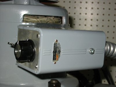
VFD Control Box
Photo by Kay Fisher
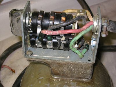
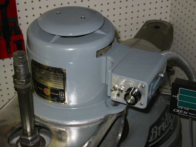
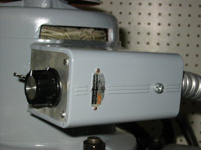
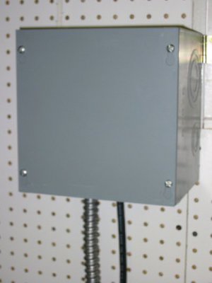
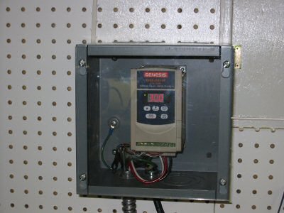
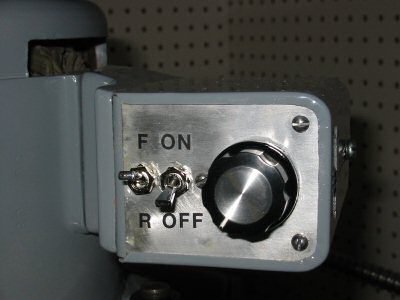
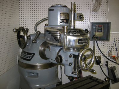
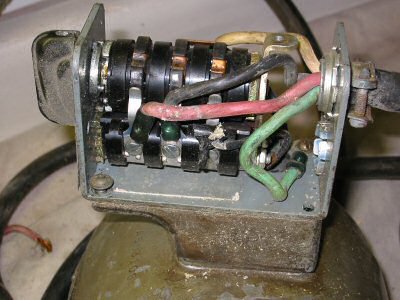
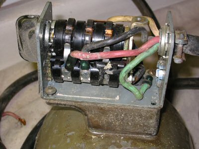
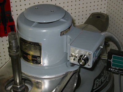
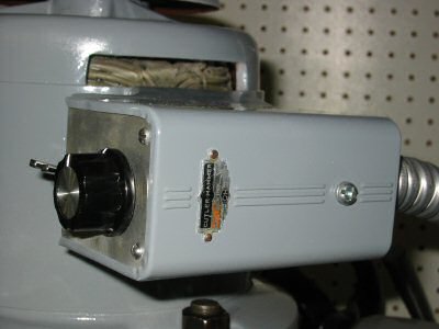
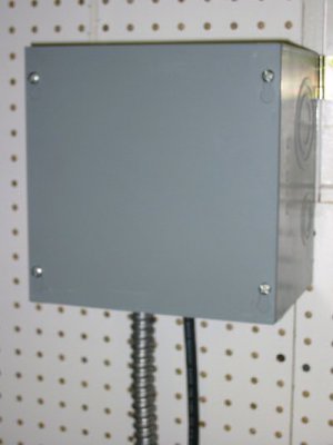
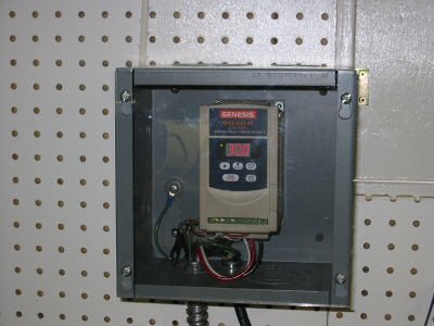
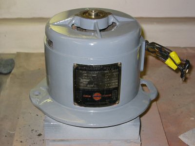
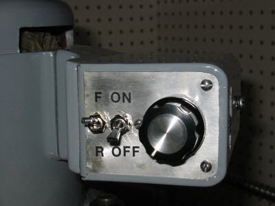
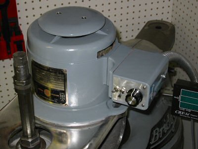
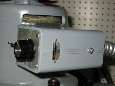
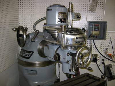
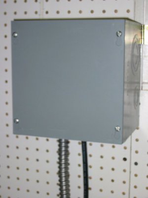
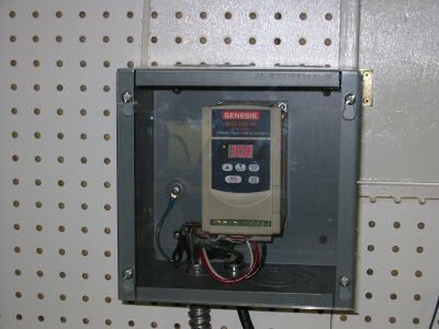
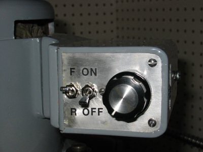
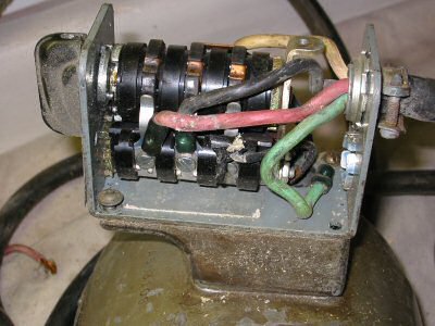
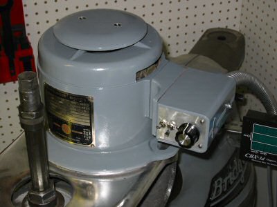
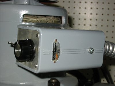
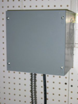
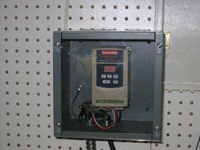
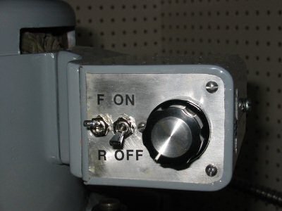
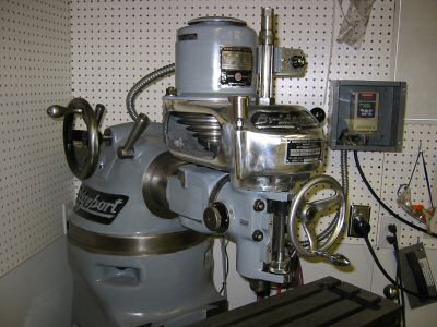
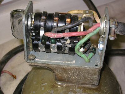
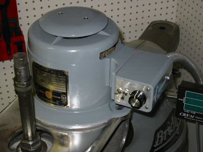
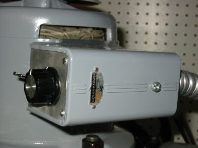
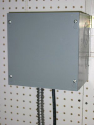
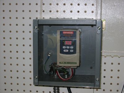
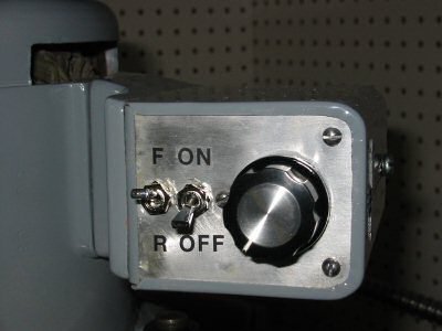
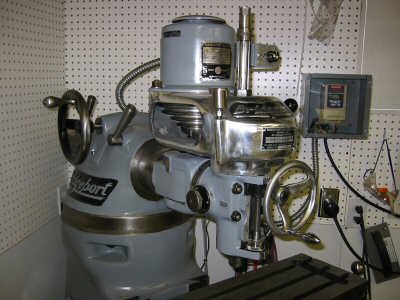
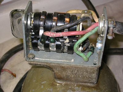
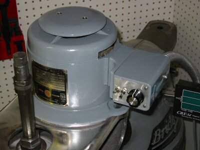
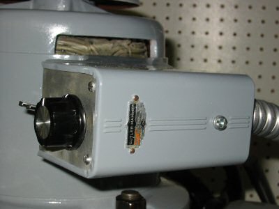
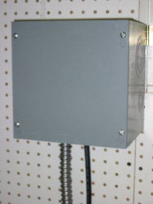
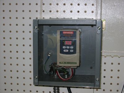
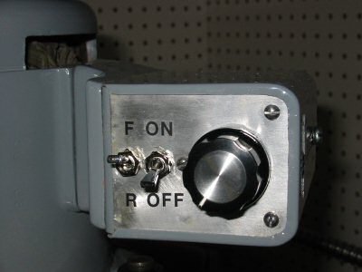
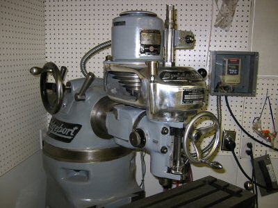
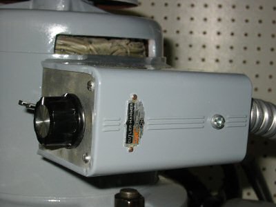
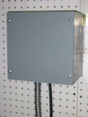
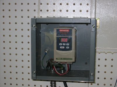
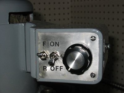
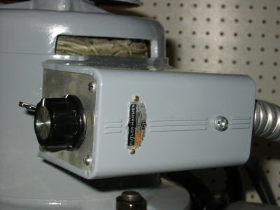
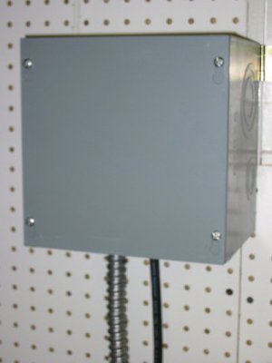
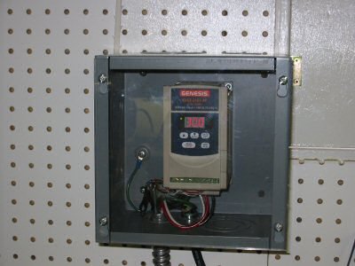
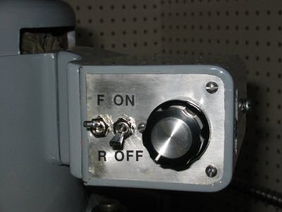
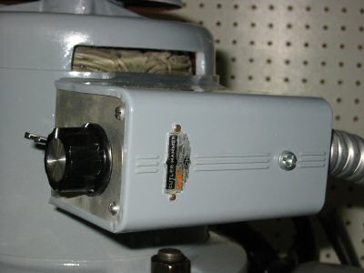
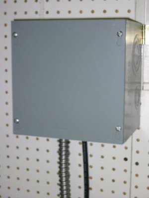
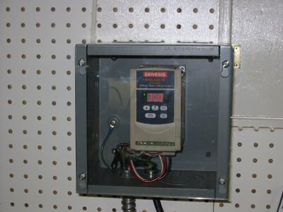
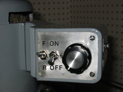
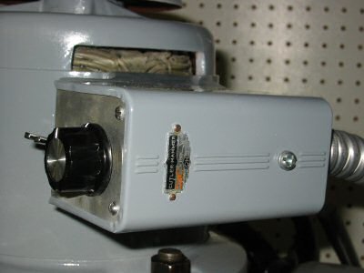
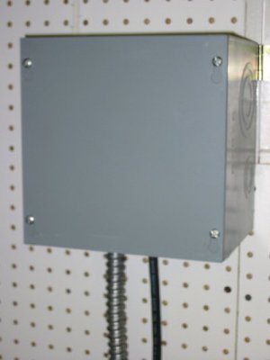
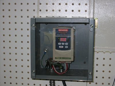
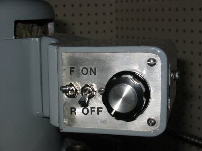
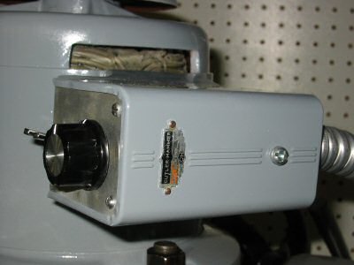
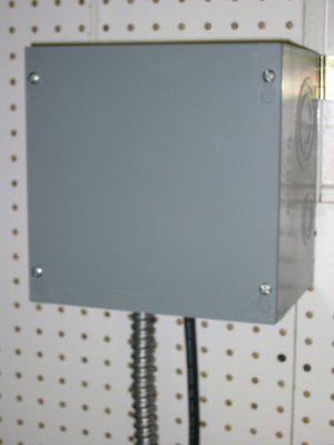
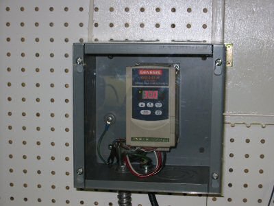
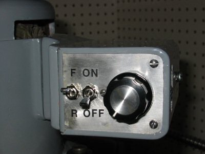
Almost all VFDs allow for external controls. I mounted two toggle switches and a potentiometer inside the old Cutler Hammer forward/reverse switch housing. To insure that the vent holes of the VFD did not ingest some swarf I mounted the control unit in a standard electrical junction box. I replaced the junction box metal front panel with Plexiglas. Not only does this protect the VFD but it also makes it silent. Before I put it in the junction box you could hear the little cooling fan inside the VFD. It is comforting that the motor, belt, and bearings of the mill are so quiet that the VFD fan could be heard.
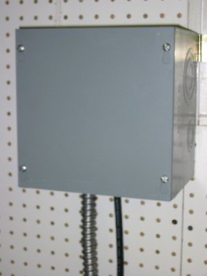
Junction Box
Photo by Kay Fisher
The junction box must be large enough that the VFD can circulate air and not overheat!
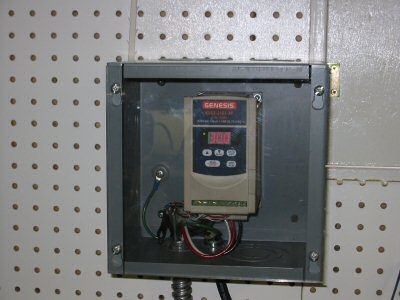
Junction Box with Plexiglas
Photo by Kay Fisher
I used rub on dry transfer labels for the front of the control unit. You can set the high and low frequency limits as well as things like the maximum current before overload protection on this VFD. This unit is rated for 1-horsepower but since I have a ½-horse motor, I adjusted the overload protection lower. You can also program the acceleration and deceleration time of the motor. I set mine to a minimum of 16 Hz and a maximum of 80Hz – which means I can run the old motor 33% faster than rated speed.
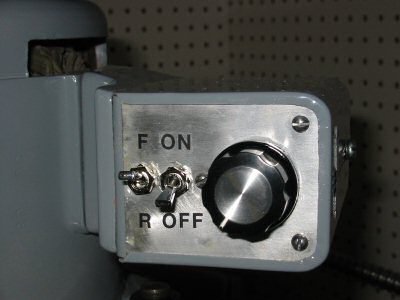
VFD Controls
Photo by Kay Fisher
KayPatFisher@gmail.com.
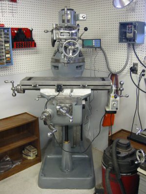
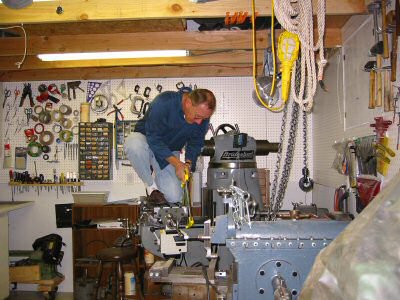
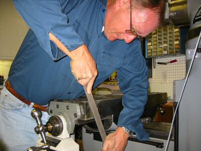
by Kay Fisher
Errol accepts cash, check, money order and PayPal. He has shipped out about 150 copies and has yet to have anyone ask for a refund.
Latest CD Contents as of 14 Jan 2003
Bridgeport Manuals
1981 Programming Manual
1983 Programming Manual
R2E3 Manual
Series II NC Programming Manual
Student Manual
Bridgeport Series 1 Install, Operate and Maintain
Manual
Quick Change Tooling for the J Head
Brown and Sharpe
No. 3 Mill Manual
Fundamentals of Machine Tools
Grinding and Lapping
1907 Treatise on Grinding and Lapping
Grinding Dressers
J and S Fluidmotion
Optidress Manual
Selecting the Right Grinding Wheel (Norton)
Tangential Wheel Dresser
Jacobs Chuck
Jacobs Rubber Collet Chuck
Leblond 15 and 19 Inch Lathes
Leblond Manual
Machinery Repair
Odds and Ends
Thread Elements Jones and Lamson
Shaper Work
Shapers - Chapter 1 and 2 Machine Tool Operation
Errol Groff
180 Middle Road
Preston, CT 06365 8206
Errol Groff
Instructor, Machine Tool Department
H.H. Ellis Technical School
(860) 774-8511
Home Page:
http://pages.cthome.net/errol.groff/
One source for Bridgeport information is the Yahoo group “Bridgeport_Mill” which you can join at http://groups.yahoo.com/.
Another is Tony Griffiths’ machine tool information website. This site has information about many machines, including lathes and mills. The Bridgeport area includes descriptions of accessories that haven’t been made in years:
www.lathes.co.uk/bridgeport
Serial Numbers
This chart is a cross reference from Bridgeport serial numbers to date of manufacture including an estimate of the number produced each year:
Round Ram
Year Serial Number Range # Made
1938 BH-1 thru BH-39 39
1939 BH-40 thru BH-252 213
1940 BH-253 thru BH-656 404
1941 BH-657 thru BH-1549 893
1942 BH-1550 thru BH-2943 1394
1943 BH-2944 thru BH-4105 1162
1944 BH-4106 thru BH-4997 892
1945 BH-4998 thru BH-5930 933
1946 BH-5931 thru BH-7235 1305
1947 BH-7236 thru BH-8814 1579
1948 BH-8815 thru BH-10381 1567
1949 BH-10382 thru BH-11378 997
1950 BH-11379 thru BH-12750 1372
1951 BH-12751 thru BH-14489 1739
1952 BH-14490 thru BH-16700 2211
1953 BH-16701 thru BH-19367 2667
1954 BH-19368 thru BH-22732 3365
1955 BH-22733 thru BH-26962 4230
Start V Ram
1956 BR-26963 thru BR-31618 4656
1957 BR-31619 thru BR-37278 5660
1958 BR-37279 thru BR-42110 4832
1959 BR-42111 thru BR-46938 4828
1960 BR-46939 thru BR-52598 5660
1961 BR-52599 thru BR-58552 5954
1962 BR-58553 thru BR-64987 6435
1963 BR-64988 thru BR-71981 6994
1964 BR-71982 thru BR-79538 7557
1965 BR-75939 thru BR-88180 8642
1966 BR-88181 thru BR-98089 9909
1967 BR-98090 thru BR-108351 10262
1968 BR-108352 thru BR-118640 10289
1969 BR-118641 thru BR-131778 13138
1970 BR-131779 thru BR-138139 6361
1971 BR-138640 thru BR-143350 5211
1972 BR-143351 thru BR-149294 5944
1973 BR-149295 thru BR-157909 8615
1974 BR-157910 thru BR-167652 9743
1975 BR-167653 thru BR-174083 6431
1976 BR-174084 thru BR-180697 6614
1977 BR-180698 thru BR-188559 7862
1978 BR-188560 thru BR-196987 8428
1979 BR-196988 thru BR-206296 9309
1980 BR-206297 thru BR-216473 10177
1981 BR-216474 thru BR-227523 11050
1982 BR-227524 thru BR-231700 4177
1983 BR-231701 thru BR-235985 4285
1984 BR-235986 thru BR-241350 5365
1985 BR-241351 thru BR-246659 5309
1986 BR-246660 thru BR-248551 1892
1987 BR-248552 thru BR-250531 1980
1988 BR-250532 thru BR-252874 2343
1989 BR-252875 thru BR-255463 2589
1990 BR-255464 thru BR-257888 2425
1991 BR-257889 thru BR-259897 2009
1992 BR-257898 thru BR-262188 2291
1993 BR-262189 thru BR-264586 2398
1994 BR-264587 thru BR-267635 3049
1995 BR-267636 thru
The main serial number, shown in the above chart, is located on the top of the knee in the front. Mine is #7365, which did not include the “BH” prefix. To expose the serial number, crank the saddle back towards the column until the chip guard plate slides back an inch. My Bridgeport was manufactured in 1947 – the same year I was born.
The door contains the full serial number BH7365, which matches the knee. It also has a patent number 2275291, which matches one on the table. The Saddle has a serial number on the left side next to the table lock handle. It should match the table serial number. Mine is #527. I don’t remember where the table serial number is. I suspect it is under the left or right bearing bracket. It really doesn’t matter as it was used during assembly at the factory to insure the surfaces that were hand scraped match up on the same machine. The table also has a patent number on the front center. Mine is #2275291. If anybody knows for sure where the table serial number is please let me know and I’ll update this paragraph.
Each dial and handle is stamped with an A, B, C, or D. The left handle and dial are A. There is also an A on the front left of the table. The right handle and dial are B. There is a B on the front right to match. The cross feed (Y axis) handle and dial are C. The elevating (Z axis) dial is D. They are machined to match and won’t fit as well anywhere else.
The M-Head serial number is on the left of the quill housing. Mine is #M21472. It should match the serial number on the belt housing.
The belt-housing serial number is on a label fastened to the front of the housing. Mine is #M21472. It should match the M-head serial number.
Not all motors have serial numbers. They changed type and manufacturers of motors over the years. Mine has a serial number on a label on the front of the motor. It is #3064.
http://www.hqtinc.com
They have an excellent catalog. You have to order from “High Quality Tools” through a distributor. I have ordered through:
Spare Parts
Spare parts for Bridgeport mills are available from many places. My favorite for new parts is High Quality Tools.
High Quality Tools, Inc.
34940 Lakeland Boulevard
Eastlake, Ohio 44095
(877) 372-9227
http://www.hqtinc.com
They have an excellent catalog. You have to order from “High Quality Tools” through a distributor. I have ordered through:
Rice Machinery
(401) 781-3010
www.ricemachinery.com
There are always parts for Bridgeport mills for sale on eBay:
www.ebay.com
Select the category “Business & Industrial” then select the sub category “metalworking”. Then search for “Bridgeport”.
http://www.hqtinc.com
They have an excellent catalog that has a small diagram of the lube system available from Lube USA. You have to order from “High Quality Tools” through a distributor. I have ordered through:
Rice Machinery
(401) 781-3010
www.ricemachinery.com
ENCO
400 Nevada Pacific Hwy.
Fernley, NV 89408
(800) 873-3626
www.useenco.com
Trico Mfg. Corp.
1235 Hickory Street
Pewaukee, Wi 53072-3999
(262) 691-9471
www.tricomfg.com
Lube USA
780 Congaree Road
Greenville, SC 29607
(800) 326-3765
www.lubeusa.com
Here is the part list of the items that I bought from Lube USA.
Qty
Part #
Item Description
Price Each
1
185052
HTG-0 Flow Adapter
$13.09
1
185002
HAS-0 Flow Unit
$7.29
1
186101
Elbow Connector
$2.94
11
106271
Tubing Insert 4mm
$0.41
13
106254
Compression Sleeve 4mm
$0.31
7
186252
Compression Bushing
$0.70
6
186251
Compression Nut
$0.70
4
106901
Tube Ends Elbow, Drive 3mm
$3.77
10ft
106801
4mm Nylon Tubing, Natural
$0.50
1
185009
HJB-0 Flow Unit
$7.29
4
185010
HJB-1 Flow Unit
$7.29
1
186404
PJ-7S Junction
$13.09
1
106707
12" Flexible Hose 300mm
$13.99
1
186420
PJ-3 Junction
$4.14
2
186255
Closure Plug
$0.69
UPS shipping
$8.58
Total
$138.67
The part numbers that start with 106 are metric. The part numbers that start with 185 and 186 are English. The output from the Bijur lubricator is 1/8” NPT as are the Bridgeport zerk oilers.
The list above is correct to the best of my knowledge. Originally I was a couple of items short and had to pay additional shipping cost for a couple of small parts. I advise anyone ordering to order extra compression sleeves, tubing, and drive barbs to allow for mistakes
Measuring and Layout
The new Bridgeports have 12 inches of Y travel where mine has 9 inches of travel. I measured a new Bridgeport mill and the lubricator was approximately 10.25” down from the top of the knee to the top of the lubricator and 4.5” from the back of the knee to the back of the lubricator.
Because my knee is smaller I placed my lubricator 7.25” down from the top of the knee and 4.25” from the back. I mounted all my hardware on the mill by drilling and tapping ¼x20 holes.

Lube System and Junction
Photo by Kay Fisher
I also measured and stared at the flexible hose for quite a long time before I decided that I did not need the 14” flexible hose and instead ordered a 12” hose.
I also got a good diagram for a 9 point lubrication system from
Bijur Lubricating Corporation
50 Kocher Drive
Bennington VT 05201-1935
(800) 631-0168
www.bijur.com

5 Port Junction on Saddle
Photo by Kay Fisher
The junction should be located as close to the knee ways as possible because the tubing must make a sharp bend through the new drilled and reamed ¾ inch hole into the top of the saddle. I wish I had positioned mine about ¼” closer to the saddle.

Saddle With Holes Drilled
Photo by Kay Fisher
Instead of running the lines to the old zerk holes, I cross-drilled into the existing oil paths and installed (hammered in) drive barbs (elbow connectors) as per Michael Morgan’s suggestion. To make sure I didn’t miss the existing oil passageways, I inserted brass rods through the old zerk holes and made sure that my measurements agreed with my line of site observations.

View of Saddle for Drilling
Photo by Kay Fisher
I asked on the phone what size hole to drill for the drive barbs. The Lube USA fellow said 1/8”. This is correct for the barb but I drilled a couple sizes smaller and worked my way out to 1/8”.

View of Saddle Plumbing
Photo by Kay Fisher
To drill in the sides of the saddle I had to use a 90 degree drill adapter and screw machine (stubby) drill bits. I just barely had room. If you don’t have a screw machine drill bit you can easily just grind off the end of a cheap bit and make one.
One of my critical holes ended up just a bit little too large. I could have ordered the next size larger barb but instead I put a layer of solder on the old one and then it fit tightly.

5/32" Tubing and Fittings
Photo by Kay Fisher
The photo above shows the 5/32” tubing with a compression nut, 4mm tubing insert and 4mm compression sleeve.
Meters
I ended up using three #0 meters and the rest #1. A #1 meter puts out twice as much oil as a #0. I put the small #0 meters on the vertical ways and on the cross feed acme screw. Now the cross feed screw gets about 7 drops of oil per cycle. The vertical ways create the biggest mess so I am glad I took Michael Morgan’s advice and put #0 meters on them. I think since they are not under pressure from the weight of the table and because the knee moves less frequently they require less oil.
Feed Nut Lubrication
To get oil into the feed screws there is a hole on top of the feed nut bracket. Normally you center the table (with a mark on the saddle), remove a set-screw in the middle of the table and drip some oil through the hole.

Feed Nut Bracket With Bondo
Photo by Kay Fisher
I used bondo to fasten the 5/32 inch nylon tubing to the top of the feed nut bracket. Bondo was my second method of fastening. My first was not successful.

Measuring for Feed Nut Oil
Photo by Kay Fisher
After I fastened the tubing to the bracket I got to thinking it might not clear the bottom of the table. In the photo above I set up some 1 2 3 blocks and measured the depth across the entire bottom of the table. It was just a hair more than 5/32”. In hind site I should have ground a groove in the feed nut bracket with a Dremel tool and laid the tubing in it to have more free space.
Modifications
In my case I elected to modify the original parts list from Lube USA “9 point lubrication system” for three reasons.
- I had an older mill with only 4 oil zerk fittings on the saddle.
- I wanted to keep it clean so that adding a power X drive and limit switches wouldn’t have me cursing the plumbing job, so I eliminated the outside plumbing on the saddle.
- I had the saddle completely apart and it would never be easier.

Bondo Two Lube Lines
Photo by Kay Fisher
I also used Bondo to fasten two lube lines that wanted to ride up as shown in the above photo.
Next Time
I would do a few things differently if I had to do it again. I would change the layout on the left side of the knee to more closely match the layout pictured in the old Bridgeport manual that comes in Error Groff’s CD “Shaper Work Plus”. The meter on the left side of the saddle sticks out further than the elbow and meter on the right side of the saddle. If I laid out the lines as per the Bridgeport picture I could make the left like the right.

Lubricator Layout
Photo from Bridgeport Manual

Lube on Right Side of Knee
Photo by Kay Fisher
I would like to have used brass tubing even though it would have been a bit harder to work with.
Way Oil
There has been much discussion on the internet about the proper oil to use. Some have used 30-weight non-detergent motor oil. Some have used chain saw bar oil. I am using “Tru-Edge” brand special way oil 68. I purchased a gallon of it years ago long before I ever had a milling machine. However, the consensus is that the best choice is Mobil Vactra #2 way oil. If I ever run out of my current supply I plan to switch to Mobil Vactra #2. It is ISO grade 68 (SAE-20) and available for $13.82 a gallon as part number 60002151 from:
MSC Industrial Supply Co.
75 Maxess Road
Melville NY 11747-9415
(800) 654-7270
www.mscdirect.com

System With Oil in Lines
Photo by Kay Fisher
There is an advantage to the nylon tubing. It was very reassuring to see the way lube travel up the clear plastic tubes on all seven of the lines.
Eliminating Zerk Holes
Last but not least – the job isn’t done until the zerk oil holes are plugged. I thought I might want to leave them in as an emergency way of supplying lube. Then I thought I might want to insert plugs made like set screws for easy removal. Finally I decided I just wanted the front to look as nice as possible with little evidence of the previous oil holes. I inserted four 1/8 NPT pipe plugs, ground the heads off with a Dremel wheel, and filed the stub down flush with the saddle.

Oil Zerk
Photo by Kay Fisher

1/8" NPT Plug
Photo by Kay Fisher

Plug Ground Off by Dremel
Photo by Kay Fisher

Plug After Filing Down
Photo by Kay Fisher
I am very happy with the one shot lube system. Now it is easy to oil and much more elegant!
www.star-techno.com

DRO Z Axis
Photo by Kay Fisher
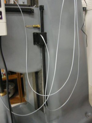
One advantage of the Shooting Star system is that you can cut each scale to the exact length required. By comparison, DROs using glass scales can be cut, but cutting the scale voids the warranty.
For this machine, I bought a three-axis DRO. Some people put the third axis on the head. I chose to put it on the column. I plan to install a cheap digital indicator on the head later.

DRO Y Axis
Photo by Kay Fisher
The DRO installation was straightforward and much easier than the installation on my Clausing mill.

DRO X Axis
Photo by Kay Fisher
On the backside of the table there were two large coolant system drain holes. I plugged these before installing the X-axis. They were ½ inch NPT so I bought a couple of plugs at the local hardware store. They only went in a couple of turns so I tapped the holes deeper. To avoid the cost of a tap I turned a cheap plug into a tap by grinding a slot in it. I installed the plugs and sawed the ends off. Then I filed the stubs flush to the table.

Plumbing Plug Tap
Photo by Kay Fisher

Cutting Head Off Plug
Photo by Kay Fisher

Cutting Head off Plug - Closeup
Photo by Kay Fisher

Filing Plug
Photo by Kay Fisher

Finished Plug
Photo by Kay Fisher

DRO Mounted
Photo by Kay Fisher
www.harborfreight.com

Custom Bushing and Bearing Race
Photo by Kay Fisher
The custom bushing (the left item in the above photo) was the only part I had to manufacture. The item on the right was the bearing race that came with the power drive. The bushing inside diameter is for a sliding fit over the longitudinal feed screw. The large outside diameter was some random scrap diameter. This is only needed to give a shoulder to the smaller end, which is a sliding fit with the supplied bearing race.

Custom Bushing and Bearing Race on Shaft
Photo by Kay Fisher

Bushing and Bearing Race Slid Home
Photo by Kay Fisher
The length of the bushing was such that the end result of the placement of the new bearing race was in line with the end of the roller bearing in the power drive as shown in the next two photos.

Power Feed Mounted
Photo by Kay Fisher

Bearing Aligned with Race
Photo by Kay Fisher
At this point in time I had a mounted power drive but needed to add two keyways like the original shaft except closer in.

Feed Screw with Dial Installed
Photo by Kay Fisher
In the photo above I mounted the brass bevel gear, dial, and dial lock nut so that I could make a mark on the shaft with a felt tip pen to determine where I would cut the first keyway.

First Keyway (On Left Above Yellow Label)
Photo by Kay Fisher
I cut the keyways with a cutting wheel on a Dremel tool. It was crude but it worked. I would have liked to cut it with my mill but I sold my Clausing and had to get my Bridgeport running before I could do any milling.

Ball Crank Handle Mounted
Photo by Kay Fisher
Next I mounted the ball crank handle so that I could again mark the location with a felt tip pen and cut the next keyway.
Next comes the moment of truth where I finally cut the end of the feed screw off with my hack saw. There is no turning back now.

Shortened Feed Screw
Photo by Kay Fisher
If I had a lathe large enough to handle the long feed screw, I would have used it to cut the threads. I didn't, so instead I cut threads the hard way.

Filing Feed Screw
Photo by Kay Fisher
I filed the end of the longitudinal feed screw down by hand until the outside diameter was appropriate for cutting threads for the nut that holds on the ball crank handle. I used a machinist clamp for a file guide. I would take 10 strokes with a file then rotate the handle 40 thousands on the left dial then take another 10 strokes then rotate... All the while I kept checking the diameter with a micrometer As I approached the desired diameter I took less strokes and rotated the handle 20 thousands per filing cycle.

Feed Screw Filed for Threads
Photo by Kay Fisher
To thread the end I simply used a manual die and was very careful.

Threading Completed
Photo by Kay Fisher
Below is a picture of the completed installation. When you put the nut on the shaft this is the first time you will actually compress the bevel gear against the gear in the power feed assembly. At this time you will have to add the supplied washer/shims as appropriate to get a nice freely moving mechanism. Not enough shims and the handle will take considerable force to turn and the gear will make bad sounds. Too many shims and the gear will feel really loose with too much backlash. This also adjusts the spacing that you see between power feed casting and the indicator dial. Note that the black spacer between the brass bevel gear and the handle is supplied with the power drive kit and is necessary for the handle to clear the power unit below it.

Handle Installed
Photo by Kay Fisher

Limit Switches Installed
Photo by Kay Fisher
The installation of the limit switches was simply one of bolting them in place. It was a lot harder on the Clausing.
www.kbelectronics.com
This small unit includes an RFI filter and costs $188 plus shipping. I also tried Electric Motor Service in Fremont CA (510) 651-2706. They returned my call 2 weeks later with a message from Lee that the same unit was $177.02. That’s a better price but it was too late.

VFD Control Box
Photo by Kay Fisher
Almost all VFDs allow for external controls. I mounted two toggle switches and a potentiometer inside the old Cutler Hammer forward/reverse switch housing. To insure that the vent holes of the VFD did not ingest some swarf I mounted the control unit in a standard electrical junction box. I replaced the junction box metal front panel with Plexiglas. Not only does this protect the VFD but it also makes it silent. Before I put it in the junction box you could hear the little cooling fan inside the VFD. It is comforting that the motor, belt, and bearings of the mill are so quiet that the VFD fan could be heard.

Junction Box
Photo by Kay Fisher
The junction box must be large enough that the VFD can circulate air and not overheat!

Junction Box with Plexiglas
Photo by Kay Fisher
I used rub on dry transfer labels for the front of the control unit. You can set the high and low frequency limits as well as things like the maximum current before overload protection on this VFD. This unit is rated for 1-horsepower but since I have a ½-horse motor, I adjusted the overload protection lower. You can also program the acceleration and deceleration time of the motor. I set mine to a minimum of 16 Hz and a maximum of 80Hz – which means I can run the old motor 33% faster than rated speed.

VFD Controls
Photo by Kay Fisher
KayPatFisher@gmail.com.


Attachments
Last edited by a moderator:

