Boring a cylinder

azshadeguy

Registered
Registered
Joined
Jul 16, 2017
Messages
146
I have a Honda GX390 on a generator that got water in the cylinder. I tried to clean it up but I think I need to rebore it.
The standard is 88mm.
I am wanting to overbore it .25mm
A couple of questions.
How do I set my boring head to the right size?
How do I set the angle right on the flat table?gx390.jpeg
 
You take a small cut, measure then take another cut, etc.
Sine bar is one way. If you have one.
I would bolt the base of the motor to a big plate and then tip it up on an angle and use an indicator on the cylinder head surface to get it parallel to the table of your mill. How you anchor and adjust the plate is up to you and your ingenuity.
Or you could clamp the side of the block to a big honking angle block and rotate it until the head surface indicates level.
 
Maybe. Is it long enough to fit down the entire length of the bore? Is the quill small enough to fit down the bore?
That setup will not be real rigid so you will need to take really small cuts. Could also be tough to get a good surface finish.
What is your plan to hone the surface to final size and finish?
What is the material of the bore of cylinder? Its not a hard coated aluminum is it?
 
That may get your rough cut, but how do you intend to finish hone?
also how will you center the cutter in the bore?

since you want .25mm over or appox .010 over, that means you can only bore .007-.008 at most, or .0035-.004 from each side most shops typically leave about .003 to finish hone, so there are no screw patterns left in the bore to click over and retain excessive oil to be burnt.
 
A parts store 3 stone hone will not give enough outward force to accurately hone the steel liner, the spring is just stiff enough to suport the metal that needs moved.

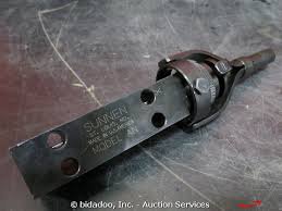
you need something along the lines of a wedge net or hear head hone
hone.jpg

This style would use Sunnen AN stones
Its the same basic style of hone head my machine uses, and pulls about 10-14 amps under load

try to keep the bore square top to bottom, less than .001, or the rings will flex to much and can crack
 
For centring a dial test indicator _could_ work, but you need to check fairly deep in the bore too, not just around the top edge to be sure you have it clamped straight.

A co-ax indicator would make it easier....the bodies are a little longer, you can use longer probes, and you don't have to chase the face of the dial around the spindle.

They are kinda spendy though....
https://www.amazon.com/BLAKE-Blake-Co-ax-Indicator-Set/dp/B005PX7QV8

-brino
 
Last edited:
The block deck should be indexed to the crank center line, so by the head gasket surface being 90* to the quill, that should set your bore close top to bottom.
then if you put a test indicator on the quill and checked the bore top to bottom and you had minimal difference in the measurement, less than .002 would be ok, this need to be measured in non ring travel area of the bore

now finding the center of the bore, would be the issue, Now if could accurately measure from the center line of the tool holder to the cutter tip, you could hand spin the cutter down the bore, as you hand crank the quill down.
the set up would have to be .001 under standard bore spec.

But I cheat when I bore a block...
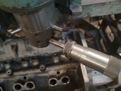
bore2.jpg
I have 3 moving fingers that centers the bore
then you can see the cutter bit and the setting mic.
 
How do I set the angle right on the flat table?

Largest flat bottom cutter you have and a ground flat piece of steel.
The cylinder deck surface is flat and square to the bore. Flat piece of steel on top the bore and engine block held up flat to your largest flat item in the quill, bolt it solid to the table, then center the bore and bore it.
Attaching that to the table looks like no fun.
You can probably get real close to centered with an edge finder in the bore. Eye ball it then left and right find X center , then towards and away for Y center, then repeat for final centering.

For .25mm oversize it could all be honed with a rigid hone. Skip the boring.
 
Back
Top