- Joined
- Oct 30, 2019
- Messages
- 225
Someone got in touch with me and asked if I might be able to help out with their project to install different bearings into four wheelchair wheels that they were using in an agricultural project. The bearings that came in the wheels were for 1/2" axle/stub shafts but they needed to use 3/4" shaft. However, bearings to accept 3/4 shaft also had a larger OD, and therefore a need to bore the hubs out slightly.
This went fairly uneventfully except for the wrinkle explained towards the bottom of the post after the volley of pictures
Given the low risk nature of the project, the cheap amazon wheels, I thought it sounded reasonable. I used a pocket knife to take a chip off a noncritical surface of one wheel and confirmed it cut nicely, I don't know what plastic but it was reasonably hard and not gummy, but didn't feel like it had glass fiber reinforcement either. They're cheap no-name import wheels, I saw markings for the age of the dies but not the material -- it seemed like ABS, maybe reinforced with something other than glass fiber. Either way felt like it should cut decently, and there was enough material to remove that I had time to troubleshoot cutting behavior before getting to a final cut/dimension.
4 wheels, each with 2 bearings. The goal was to obtain the light press fit that the original bearings had, approximately .001 to .002 undersize from the bearing OD.
One more complication, one of the bearing pockets had been subjected to this person's attempt to open the diameter up themself by hand, with some pretty poor results -- however it did not exceed the target diameter (but was not a machined surface nor round to indicate off of)
Too big for my lathes, went for the bridgeport and used the recently-acquired secondhand boring head.
Order of ops for each side of each wheel:
Some pictures, then explanation of a hurdle below
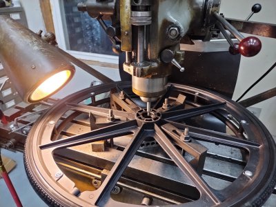
Clamped and centered, ready to change tools to the boring head
Really happy with the result. The space between the bearing pockets is not a critical dimension for their project, but I generally stopped where the original shoulder was. Also the bearings they had are flanged, probably specifically (for wheelchair usage) to help register on the hub faces instead of making the pocket depth a critical dimension.
Action shots, though these are with a bearing sitting in the hub's recess as I was testing fit
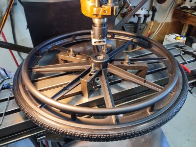
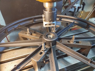
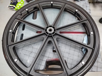
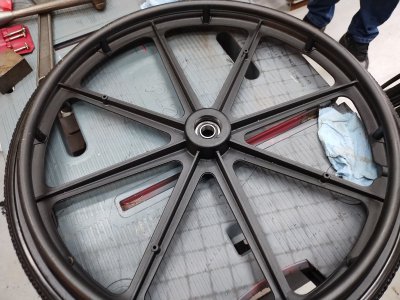
One of the sides (shown below, the "outer bearing" of the wheel ) has a counterbore molded in, then the pocket for the bearing sits lower down. Whereas the inner bearing's pocket basically starts flush with the hub of the wheel.
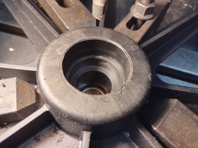
Looks pretty clean with the bearings installed, impressive die work for the injection molding on these larger parts
So the wrinkle --
The first wheel I did was going to be the one with the manual work on the pocket, but I would do the un-touched side first. That went as-described above.
But when flipped over ... what would I indicate off of? The ID of the bearing pocket was chewed up, and I did not want to trust that the injection-molded, tapered (relief /clearance/whatever angle for the injection molding die to release) outer hub surface would be concentric with the intended bearing pocket.
What about a way to indicate off the new bearing that is now installed into the other side of the wheel, facing the table? My edge finder is way too short, and I didn't break out my coax indicator because I don't think I have the bits for it to reach either.
I have some 6" pieces of ground rod that I occasionally use for testing runout in various workholding setups.... I mean that's overkill for this (anything straight would do) but straighter is better.
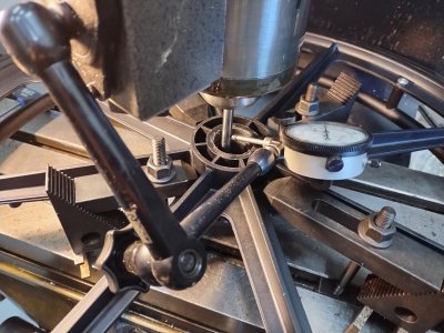
I figured I could use any straight piece of rod in a collet in the spindle as an edgefinder. The trick is seeing through the hub and telling when it just makes contact - no way to get a feeler gauge or paper down in there , or enough light and a mirror.
So ....
What about using this 6" rod, and watching for deflection as soon as the table travels enough that we hit the inner race of the bearing on the far side? By putting an indicator against it, and putting the indicator as low down as possible (to read the most deflection instead of nearer the collet where there would be minimal deflection)... this should work. and if I test to the point of the same deflection (like 0.001" on the indicator) when I travel to the + and - of a given axis, the "just divide by 2 to find the center" will still work out on the DRO.
In short, it worked perfectly. I barely spent any more time on this chewed up pocket than I did on the others, the whole task was completed in around 3 hours from initial description to cleanup
Thanks for reading
This went fairly uneventfully except for the wrinkle explained towards the bottom of the post after the volley of pictures
Given the low risk nature of the project, the cheap amazon wheels, I thought it sounded reasonable. I used a pocket knife to take a chip off a noncritical surface of one wheel and confirmed it cut nicely, I don't know what plastic but it was reasonably hard and not gummy, but didn't feel like it had glass fiber reinforcement either. They're cheap no-name import wheels, I saw markings for the age of the dies but not the material -- it seemed like ABS, maybe reinforced with something other than glass fiber. Either way felt like it should cut decently, and there was enough material to remove that I had time to troubleshoot cutting behavior before getting to a final cut/dimension.
4 wheels, each with 2 bearings. The goal was to obtain the light press fit that the original bearings had, approximately .001 to .002 undersize from the bearing OD.
One more complication, one of the bearing pockets had been subjected to this person's attempt to open the diameter up themself by hand, with some pretty poor results -- however it did not exceed the target diameter (but was not a machined surface nor round to indicate off of)
Too big for my lathes, went for the bridgeport and used the recently-acquired secondhand boring head.
Order of ops for each side of each wheel:
- Place on the table with a 123 block under the hub
- Clamp around the hub with strap clamps, lightly and tightening gradually in sequence to snug but not break anything
- Use an edgefinder on the ID to center up on the part. Coax indicator would have been more time-consuming and excessively precise for the parts and project at hand
- A couple of roughing passes for bulk material removal(I eventually settled on .006"/rev feed, .025 DOC, and "what felt right" RPM) with the boring head
- Two finish passes to balance the tool pressure and hit the target diameter of 1.376 to 1.377 (bearing OD measured 1.378, 35mm)
- Push the bearing in by hand with a socket and couple taps of a small hammer
Some pictures, then explanation of a hurdle below
Clamped and centered, ready to change tools to the boring head

Really happy with the result. The space between the bearing pockets is not a critical dimension for their project, but I generally stopped where the original shoulder was. Also the bearings they had are flanged, probably specifically (for wheelchair usage) to help register on the hub faces instead of making the pocket depth a critical dimension.
Action shots, though these are with a bearing sitting in the hub's recess as I was testing fit


One of the sides (shown below, the "outer bearing" of the wheel ) has a counterbore molded in, then the pocket for the bearing sits lower down. Whereas the inner bearing's pocket basically starts flush with the hub of the wheel.

Looks pretty clean with the bearings installed, impressive die work for the injection molding on these larger parts


So the wrinkle --
The first wheel I did was going to be the one with the manual work on the pocket, but I would do the un-touched side first. That went as-described above.
But when flipped over ... what would I indicate off of? The ID of the bearing pocket was chewed up, and I did not want to trust that the injection-molded, tapered (relief /clearance/whatever angle for the injection molding die to release) outer hub surface would be concentric with the intended bearing pocket.
What about a way to indicate off the new bearing that is now installed into the other side of the wheel, facing the table? My edge finder is way too short, and I didn't break out my coax indicator because I don't think I have the bits for it to reach either.
I have some 6" pieces of ground rod that I occasionally use for testing runout in various workholding setups.... I mean that's overkill for this (anything straight would do) but straighter is better.
I figured I could use any straight piece of rod in a collet in the spindle as an edgefinder. The trick is seeing through the hub and telling when it just makes contact - no way to get a feeler gauge or paper down in there , or enough light and a mirror.
So ....
What about using this 6" rod, and watching for deflection as soon as the table travels enough that we hit the inner race of the bearing on the far side? By putting an indicator against it, and putting the indicator as low down as possible (to read the most deflection instead of nearer the collet where there would be minimal deflection)... this should work. and if I test to the point of the same deflection (like 0.001" on the indicator) when I travel to the + and - of a given axis, the "just divide by 2 to find the center" will still work out on the DRO.
In short, it worked perfectly. I barely spent any more time on this chewed up pocket than I did on the others, the whole task was completed in around 3 hours from initial description to cleanup

Thanks for reading
Last edited:

