- Joined
- Oct 30, 2019
- Messages
- 225
Higher-res pictures are attached, click on any thumbnail
For a while I have wanted more "press" capability in the shop, but I don't currently want to spend my remaining floor space on a floorstanding press.
Someone asked me if I had a press to help them test a die for some jewlery project, and that inspired me to finally build a benchtop one this past weekend (prepared some of the parts over the last week and assembled this weekend)
Source material:
- Bottle jack that appears to have at some point been from a Ford pickup based on the label showing positioning under various F-series frames. I'm guessing 5-6 ton based on the proportions of the jack
- Plate steel scraps from my friend's back yard of junk
- Rod salvaged from the front struts of our prius when I replaced them a few years ago
- Bearing bronze (not oilite), this was leftover new material from some past project, (from my mcmaster order history it looks to be 544 bronze)
- Spings salvaged from a broken trampoline a neighbor had a few years ago
- Various other bits of steel
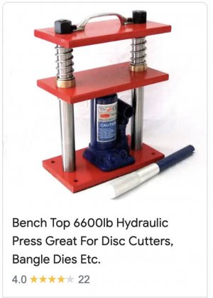
The goal was to emulate this general design:
First I needed to decide which rods would be used as guide rods, from a variety of struts and shocks in my scrap pile:
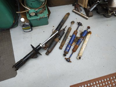
I opted for the prius struts because the rods were the thickest, and threaded on at least one end which could help assembly. Started by drilling a small hole to drain the oil from the bottom, angling the strut so that hopefully a gas bubble would be where I break through instead of shooting some oil out, but this wasn't a highly pressurized strut in the first place
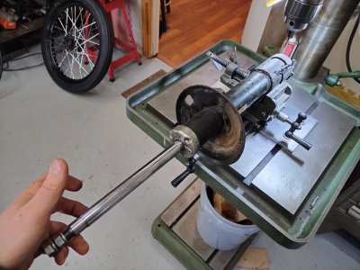
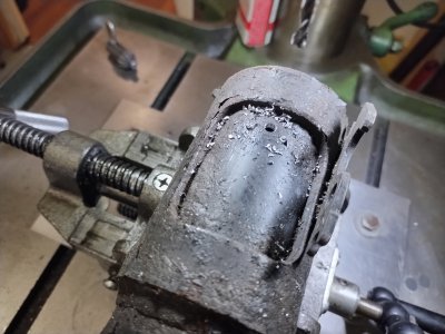
Drained the oil, I did a couple of the other thinner/longer ones as well in case I found I wanted secondary or longer guide rods
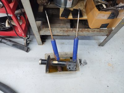
Then cut the bottom of the strut off with the portaband to expose the bottom of the rod and pull it apart. On the first one I ended up cutting through a lot of the hardware at the bottom, on the second one I managed to cut through tubing and avoid the hardware
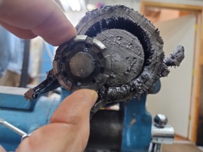
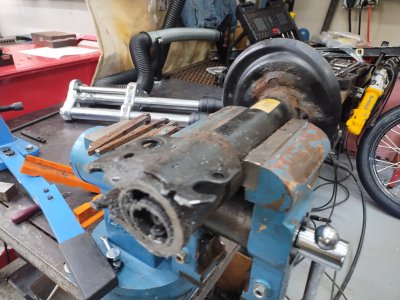
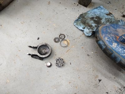
It turned out the rod was threaded at both ends, which could be handy.
Lots of thin spring steel reed valve type pieces and shims in the bottom of these, saved those since they could be handy in the future
I worked the design/build from the bottom up, tacked a few 1" bars to the bottom of the steel base plate for extra weight and rigidity
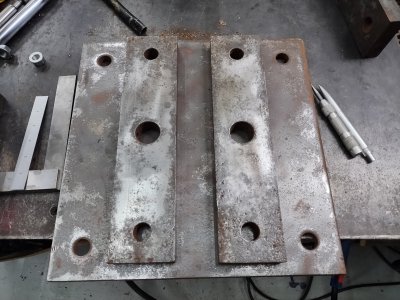
Then took it to the mill to drill holes on the center of the holes for the guide rods.
The 1" steel bars I had on hand were from an unknown origin, but they had a larger hole in the middle as well as 1" holes that were 10.1" apart. I decided I would use those existing ~.750" (overszied) holes for the guide rods, so that set the spacing of the holes in the base plate for where the guide rods would be installed.
The rod from the prius was 12mm on the end I decided would be the bottom, so these were 12mm holes.
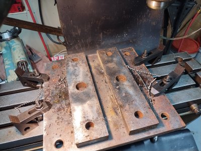
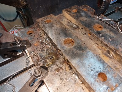
I figured I would come back later and deck these bottom bars for a flat bottom, but only after finishing welding them on since I would expect things to distort.
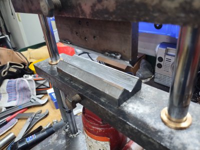
Next I bored out the guide holes in what would become the moving jaw. I wanted to clean them up from their original rust, going large enough that the guide bushings would have reasonable substance to them. The holes were 0.775 to 0.800 originally, so I used a twist drill to open to 1".
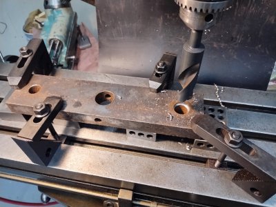
Then bored for the bushings.
The bearing bronze I had on hand is 1.25", and ideally I'd keep around .1" wall thickness on the bushing with the rod being .785" (20mm). so I brought the bores on the bar to 1.075" - just enough to clean it up, take some balanced cuts to get them round and on the known 10.1" center via the DRO on the mill.
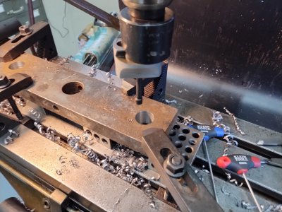
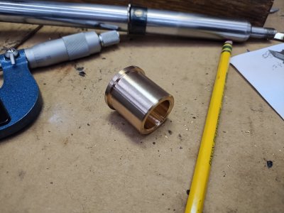
Next the bushings, I didn't take pictures because it went pretty quick and uninteresting. I aimed for .0005 to .0001" press fit on the outside and .001" to .002" clearance on the inside, with room for error:
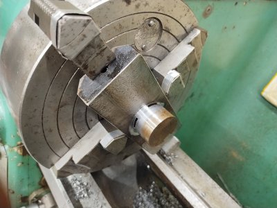
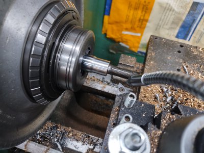
Final assembly was pretty straightforward, with one more machining step left. I wanted enough thread protruding through the top jaw to double-nut it the same way it was in situ in the car, so I turned off an extra intermediate diameter on the end of each rod down to 12mm to match the major diameter of the threads.
Here is the "before" picture, I didn't get an "after" - but the portion from the base of the threads to the right side of the small taper was removed.
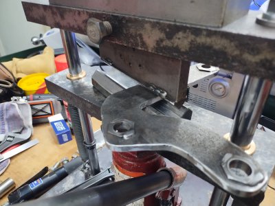
This also gave me a larger flat shoulder for the top jaw to be clamped against. However, the rod is .785" and the existing holes in the top jaw are the same size give or take .020" -- so I made some flanged bushings to clamp against. The flange only sees the clamping load from the nuts at the top, not the press load - so this didn't need to be overkill. I left the original rusty hole alone and just made the a loose clearance fit since none of the geometry at the top was super critical. If anything, a bit of "float" so this can self-align instead of constraining the guide rods could be desirable.
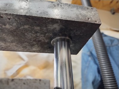
I didn't get a picture at the time, here is one of those flanged bushings under the top jaw
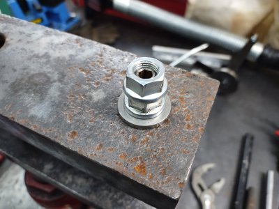
And the double-nutting on top with the factory threads and nuts:
Now I just needed to do final assembly and I welded in some half-links of chain to hold the springs to help retract the lower jaw:
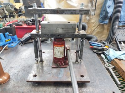
Really happy with the bronze bushings, the chamfer on the inside of them holds a nice ring of oil around the rod during its usage
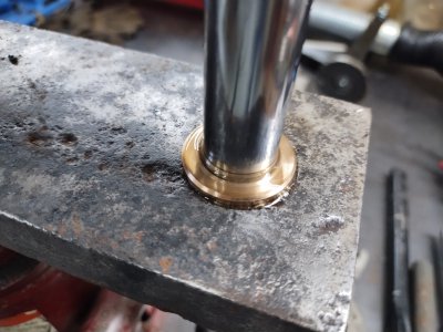
One problem that came up, and is probably for the better.... the threads on the bottom of the rods were getting chewed up and eventually stripped off just by putting this together twice. When Toyota or their OEM for these struts put the piston together on the rod, they deformed the nut to ensure it would never back off inside the cylinder. As a result, it was galling the threads badly. I also didn't feel great about trusting those threads from the start, so once they stripped I didn't feel bad welding the rods to the bottom. I could weld them from above and below the plate, making for a very solid connection.
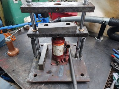
What's left? Just to finish welding in those bottom plates under the base.
Oh, distortion. All that weld on the bottom of the plate caused it to bend downward, completely ruining the geometry of the guide rods. The bottom of them were on 10.1" centers of course, but the top was almost 1/4" wider - the moving jaw was binding badly as it got pressed upward.
I was considering my options.... I could go to a neighbor's house and use a bigger press to just bend the bottom plate back into shape.... I could weld a bunch on the top and grind it off to put stress in from the top to balance out the bottom... I could brute force this by squeezing the rods together until something bends.
Instead of welding on the top, I just used the OA torch to melt a puddle down the middle of the plate - you can see the discoloration in below the bottle jack in the picture above. That actually worked too well, and the top of the rods were too close together! So I did a lighter version of the same thing on the bottom, just 5 short stitches across the plate to pull it back the other way. The alignment was now good.
Oh, and because I welded the rods in, I could never go back and deck the bottom on the mill. Not a huge deal, it sits surprisingly flat anyway and I could always add some adjustable feet if I want it to sit better in the future.
I would like to know the compressive force available to me now, but haven't though of a good way to improvise a load cell while having some idea of the real-world result. I do know it's more powerful than my Dake #1 arbor press, which in theory is good for 2-3 tons (maybe 1-2 tons with me not completely going gorilla on it), but that isn't really a surprise. I don't see any particularly cheap compression load cells on the market, though I may be able to track something down I can use with a multimeter instead of a commercial display as part of the system... thoughts? any known tests that could be done of "if you can press X into Y" or "deform from A to B" then you know approximate tonnage?
Things I learned/would do differently:
thanks for reading
For a while I have wanted more "press" capability in the shop, but I don't currently want to spend my remaining floor space on a floorstanding press.
Someone asked me if I had a press to help them test a die for some jewlery project, and that inspired me to finally build a benchtop one this past weekend (prepared some of the parts over the last week and assembled this weekend)
Source material:
- Bottle jack that appears to have at some point been from a Ford pickup based on the label showing positioning under various F-series frames. I'm guessing 5-6 ton based on the proportions of the jack
- Plate steel scraps from my friend's back yard of junk
- Rod salvaged from the front struts of our prius when I replaced them a few years ago
- Bearing bronze (not oilite), this was leftover new material from some past project, (from my mcmaster order history it looks to be 544 bronze)
- Spings salvaged from a broken trampoline a neighbor had a few years ago
- Various other bits of steel
The goal was to emulate this general design:

First I needed to decide which rods would be used as guide rods, from a variety of struts and shocks in my scrap pile:

I opted for the prius struts because the rods were the thickest, and threaded on at least one end which could help assembly. Started by drilling a small hole to drain the oil from the bottom, angling the strut so that hopefully a gas bubble would be where I break through instead of shooting some oil out, but this wasn't a highly pressurized strut in the first place


Drained the oil, I did a couple of the other thinner/longer ones as well in case I found I wanted secondary or longer guide rods

Then cut the bottom of the strut off with the portaband to expose the bottom of the rod and pull it apart. On the first one I ended up cutting through a lot of the hardware at the bottom, on the second one I managed to cut through tubing and avoid the hardware


It turned out the rod was threaded at both ends, which could be handy.
Lots of thin spring steel reed valve type pieces and shims in the bottom of these, saved those since they could be handy in the future

I worked the design/build from the bottom up, tacked a few 1" bars to the bottom of the steel base plate for extra weight and rigidity

Then took it to the mill to drill holes on the center of the holes for the guide rods.
The 1" steel bars I had on hand were from an unknown origin, but they had a larger hole in the middle as well as 1" holes that were 10.1" apart. I decided I would use those existing ~.750" (overszied) holes for the guide rods, so that set the spacing of the holes in the base plate for where the guide rods would be installed.
The rod from the prius was 12mm on the end I decided would be the bottom, so these were 12mm holes.


I figured I would come back later and deck these bottom bars for a flat bottom, but only after finishing welding them on since I would expect things to distort.
Next I bored out the guide holes in what would become the moving jaw. I wanted to clean them up from their original rust, going large enough that the guide bushings would have reasonable substance to them. The holes were 0.775 to 0.800 originally, so I used a twist drill to open to 1".

Then bored for the bushings.
The bearing bronze I had on hand is 1.25", and ideally I'd keep around .1" wall thickness on the bushing with the rod being .785" (20mm). so I brought the bores on the bar to 1.075" - just enough to clean it up, take some balanced cuts to get them round and on the known 10.1" center via the DRO on the mill.

Next the bushings, I didn't take pictures because it went pretty quick and uninteresting. I aimed for .0005 to .0001" press fit on the outside and .001" to .002" clearance on the inside, with room for error:
- I would rather have the ID be too tight and use an adjustable hand reamer to open it up, than have it be too loose and allow the moving jaw to hunt/bind
- I would rather have the OD be slightly too loose and use some green locktite, than have too much press fit and chew things up

Final assembly was pretty straightforward, with one more machining step left. I wanted enough thread protruding through the top jaw to double-nut it the same way it was in situ in the car, so I turned off an extra intermediate diameter on the end of each rod down to 12mm to match the major diameter of the threads.
Here is the "before" picture, I didn't get an "after" - but the portion from the base of the threads to the right side of the small taper was removed.

This also gave me a larger flat shoulder for the top jaw to be clamped against. However, the rod is .785" and the existing holes in the top jaw are the same size give or take .020" -- so I made some flanged bushings to clamp against. The flange only sees the clamping load from the nuts at the top, not the press load - so this didn't need to be overkill. I left the original rusty hole alone and just made the a loose clearance fit since none of the geometry at the top was super critical. If anything, a bit of "float" so this can self-align instead of constraining the guide rods could be desirable.
I didn't get a picture at the time, here is one of those flanged bushings under the top jaw

And the double-nutting on top with the factory threads and nuts:

Now I just needed to do final assembly and I welded in some half-links of chain to hold the springs to help retract the lower jaw:

Really happy with the bronze bushings, the chamfer on the inside of them holds a nice ring of oil around the rod during its usage

One problem that came up, and is probably for the better.... the threads on the bottom of the rods were getting chewed up and eventually stripped off just by putting this together twice. When Toyota or their OEM for these struts put the piston together on the rod, they deformed the nut to ensure it would never back off inside the cylinder. As a result, it was galling the threads badly. I also didn't feel great about trusting those threads from the start, so once they stripped I didn't feel bad welding the rods to the bottom. I could weld them from above and below the plate, making for a very solid connection.

What's left? Just to finish welding in those bottom plates under the base.
Oh, distortion. All that weld on the bottom of the plate caused it to bend downward, completely ruining the geometry of the guide rods. The bottom of them were on 10.1" centers of course, but the top was almost 1/4" wider - the moving jaw was binding badly as it got pressed upward.
I was considering my options.... I could go to a neighbor's house and use a bigger press to just bend the bottom plate back into shape.... I could weld a bunch on the top and grind it off to put stress in from the top to balance out the bottom... I could brute force this by squeezing the rods together until something bends.
Instead of welding on the top, I just used the OA torch to melt a puddle down the middle of the plate - you can see the discoloration in below the bottle jack in the picture above. That actually worked too well, and the top of the rods were too close together! So I did a lighter version of the same thing on the bottom, just 5 short stitches across the plate to pull it back the other way. The alignment was now good.
Oh, and because I welded the rods in, I could never go back and deck the bottom on the mill. Not a huge deal, it sits surprisingly flat anyway and I could always add some adjustable feet if I want it to sit better in the future.
I would like to know the compressive force available to me now, but haven't though of a good way to improvise a load cell while having some idea of the real-world result. I do know it's more powerful than my Dake #1 arbor press, which in theory is good for 2-3 tons (maybe 1-2 tons with me not completely going gorilla on it), but that isn't really a surprise. I don't see any particularly cheap compression load cells on the market, though I may be able to track something down I can use with a multimeter instead of a commercial display as part of the system... thoughts? any known tests that could be done of "if you can press X into Y" or "deform from A to B" then you know approximate tonnage?
Things I learned/would do differently:
- I oriented the bars under the base the wrong way for rigidity in the way this actually gets loaded, ideally
- Ideally I should have finished welding those bars onto the bottom earlier, to avoid the distortion later in the finished project
- Since I had to weld the guide rods into the bottom, I never could go back and deck the bottom to sit flat on the table though it came out pretty flat/stable in the end, just not perfect.
- The bars I used for the fixed and moving jaw ideally would be more rigid (not have those holes in the center), but they seem like features that could come in handy for setups and I can add rigidity by putting other bars inside of them when I have the space for it.
- I am a bit careful with this thing for now, since I don't know if the bottle jack is strong enough it could blow the whole thing up. The weak point that risks energetic failure would be the threads at the top of the rods, so I'm happy those are double-nutted. I took this thing up to "max comfortable load" (one hand on the input lever to the bottle jack, to the point the whole thing starts to tip over), and then checked and nothing distorted - the top 2 nuts came off freely after being loosened. So I think as long as I don't bolt this to a table and put a cheater pipe on the input, it's got some margin for now. I suppose I could try adjusting the relief valve in the bottle jack to bypass at this point if I continue to be concerned.
- I'd like to add a pressure gauge to the jack maybe? dunno
thanks for reading
Last edited:

