- Joined
- Oct 30, 2019
- Messages
- 225
Last year, late spring/early summer, I brought a Bridgeport variable-speed 2J from Chicago to home in the mid-atlantic. Since then I did fix the lights and assembled a new controller for the x-axis power feed, but there were a few things still on my list to address:
The brake thing has been nagging me, it isn't a failure I expected when I bought the machine. Over the last 6-8 months I've occasionally entertained my options:
Hm, a power drawbar could be an interesting solution:
A prerequisite was to extend my air lines to the back wall of the shop, something I had been wanting to do for a while but never had good reason to do. Previously, the black pipe air lines had just been brought through the wall from the garage, into the shop, and ~2/3" down the side wall (past the lathes, small mill, to the bandsaw), since that served all the initial purposes and I could hook a hose up to reach the welding table as-needed.
With a 10' stick of black pipe, the extension to the back wall was complete. Whenever possible, I try to tilt the pipe towards a turn and allow for a drip leg combined with a drop in that corner, so I did the same here and teed out the top to turn along the back wall. This also gives a drop in the back corner of the shop where there is a workbench.
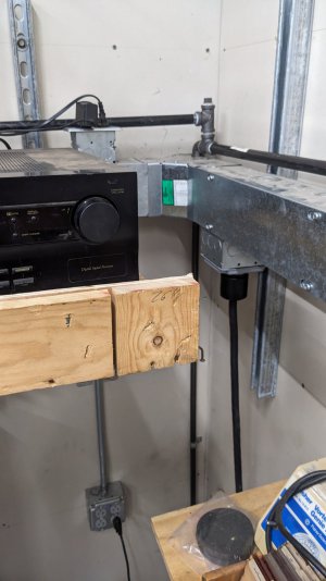
Then installed another 10' stick along the back wall, cut it a little so it would end just short of the window on the back wall, and adapted to a 3/8" pipe drop for a drip leg and quick coupler. I used a 4-way tee along the main line, because I also wanted to put a recent auction-acquired hose reel on the wall above the window
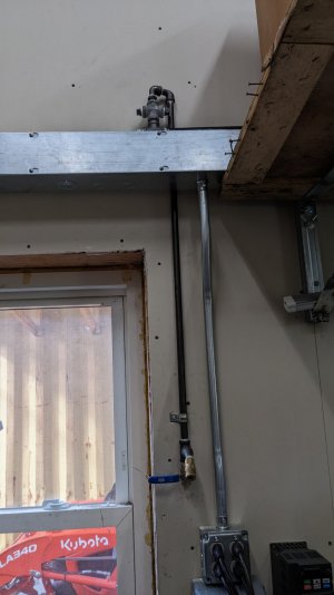
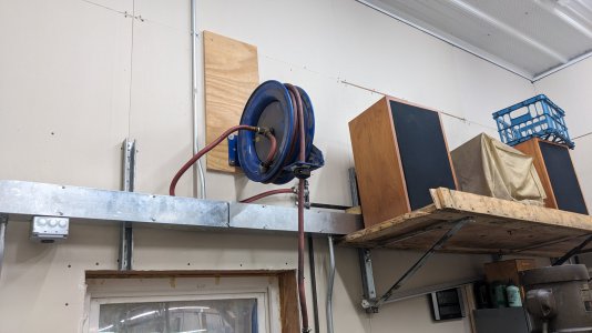
The building is a pole barn so the outside walls are not studded, but rather have horizontal stringers on 24" vertical centers. To mount the reel, I put a piece of 5/8 or 3/4" plywood scrap on the wall, which seemed to be able to handle the weight of the reel's foot (since it is mounted close to the lower stringer). Ideally the top screws for the reel's mount would be in the stringer, but that would cause it to interfere with the electrical wireway.
I won't go into detail on the install of the drawbar kit because it's covered well on youtube and in the enclosed directions, but it took 1-2 hours to fully install, and the kit included the correct drawbar for this head (H&W offer a kit for the various common head styles)
The kit did come with everything needed, including the bidirectional pneumatic controls and bracket+hardware to mount it above the quill power feed speed selector. I like that this kit allows for the controls placement here, another minor improvement over a DIY solution where the direction control generally needs to be a lever over top of the mill head.
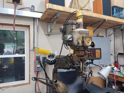
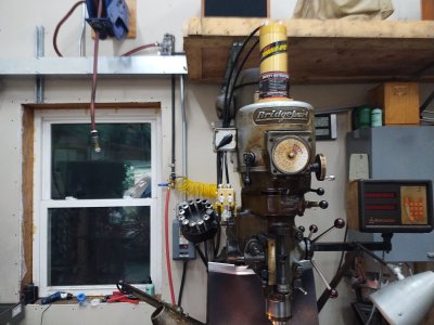
The filter-regulator-lube (that also comes in the kit along with the flexible line) mounted easily to the back of the ram by drilling and tapping two small holes. It is nice to put this on the ram so that everything moves together whenever the ram is moved.
I happened to have a piece of spiralized flexible 1/4" air line from some auction junk, and used that to go from a tee on the 3/8 black pipe drop over to the FRL, so that if I ever need to move the machine slightly or move the ram, I have all the degrees of freedom needed without changing hose length.
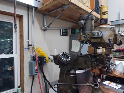
Ok, now to make some controls changes.
As-mentioned, the VFD and master power contactor are on the wall behind the machine. The original controls have a drum switch on the side of the head to change the direction of the motor (originally labeled low/high since the fwd/rev changes when the back gears are engaged).
My plan was:
Back when I added low voltage controls to the VFD for the Chipmaster lathe, I bought two of these nice cast aluminum enclosures since I was paying shipping from Taiwan anyway. In hindsight I wish I bought 4 or 5 because I can tell how use ful these will continue to be around the shop, and may order again if they're still available on ebay.
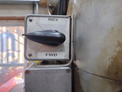
This mounts using the same hole pattern and hardware as the drum switch. While the drum switch was off, I cleaned it all up (50 years of oil and chips) and printed labels for fwd/rev (in high speed). I also knew oils would attack and cause the labels to peel off, so I made a clear insert that sits under the knob and lip of the drum switch enclosure, but covers the label plate. This was made out of some thick plastic cover from some glossy print marketing material given to us by a vendor at work years and years ago.
For some reason when I took the plastic cover off to recycle the rest of the bound paper, I decided to keep the plastic in the shop.... lo and behold I actually used a piece of it now
The bracket is 1/8" or .1" aluminum, from some scrap salvaged by the previous owner of my Chipmaster (he gave me most of his scrap pile when I bought the lathe), bandsawed, drilled with the hole pattern, and formed with my cheap import bench-mount bender.
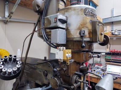
The installed the potentiometer in the cover (this aluminum casting alloy drills/machines sooo buttery smooth), leaving room for potential additional controls in the future, instead of putting the pot straight in the middle
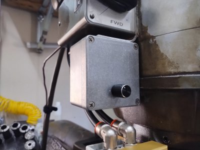
Wiring up was nothing special, but I did deliberate wire choice. On the chipmaster I used some 18/3 power cord pieces that were already available, one piece for the fwd/rev/stop and one piece for the 3-wire pot. However in this case I don't have any more of that, let alone the longer piece needed to droop back to the VFD.
Ideally this would be some 18/8 or similar-count SO cord for oil resistance, and maybe some day that's what it will become. However what I did have on the shelf was a partial role of 18/7 thermostat wire.
I used that, daisy-chaining the drum switch and new enclosure together. I slipped a piece of heat shrink tubing over the wire between the two in case it helps increase oil resistance for now, but I acknowledge that some day this will probably all harden and need to be replaced.
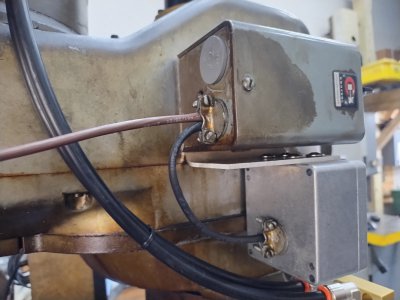
From the drum switch the wire is velcroed with the motor power cord, back to the VFD on the wall
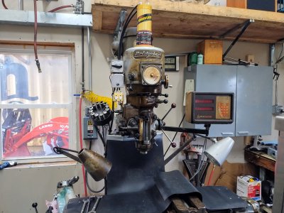
Here is the final result of the controls improvements, with the fwd/rev/stop drum switch, speed control, and drawbar all tucked together to the upper right side of the head - out of the way but in the same general area.
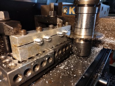
Recently when my parents were visiting, all of this got good use when I ran another small batch of parts for one of his little retirement cottage industry projects, including using the newly-repaired X-axis power feed for the slotting operation on the mill which was a nice treat.
Thanks for reading
- The VFD is mounted back on the wall behind the machine, the controls need to be extended to the operator, like I did on the Chipmaster once its VFD became wall-mounted.
- The spindle brake is kaput, making tool changes annoying (requiring me to switch into low gear for every tool change as a stand-in for the brake)
- Does the one-shot lube system work? I didn't address that in this thread but wanted to mention it in case anyone has suggestions on what to look for to evaluate if it is fully working. I don't think I even have an idea of all the points that system extends to with its spider of lines
The brake thing has been nagging me, it isn't a failure I expected when I bought the machine. Over the last 6-8 months I've occasionally entertained my options:
- Open the head and only fix the brake (it barely introduces drag, so it's either worn or damaged)
- If the brake is buried and requires removing most of the components in the head, might as well rebuild the head
- However I have concerns about doing a full head rebuild if I don't do it in a short period of time, with parts and information spread out
- Or really treat myself... send the head out to get rebuilt by someone like H&W, which would cost about what I paid for the machine but of course would last the rest of my lifetime
- Or just keep dealing with it.
Hm, a power drawbar could be an interesting solution:
- I am not a tall person, tool changes have always been a stretch - I barely get away without needing a block or stool to step on
- A power drawbar would obviate the need for a brake (or switching to low gear) for tool changes
- Also since I use the VFD, the VFD already brakes the motor when slowing or stopping -- so I have never been like "man I wish I had a brake to stop the spindle from coasting for too long"
- I could build a power drawbar, as many others have done, and keep the budget down
- But a decent power drawbar kit would be in the same ballpark (low-mid "hundreds") as everything needed to do a full head rebuild myself, without the risk of getting fully into the head myself just for the brake.
A prerequisite was to extend my air lines to the back wall of the shop, something I had been wanting to do for a while but never had good reason to do. Previously, the black pipe air lines had just been brought through the wall from the garage, into the shop, and ~2/3" down the side wall (past the lathes, small mill, to the bandsaw), since that served all the initial purposes and I could hook a hose up to reach the welding table as-needed.
With a 10' stick of black pipe, the extension to the back wall was complete. Whenever possible, I try to tilt the pipe towards a turn and allow for a drip leg combined with a drop in that corner, so I did the same here and teed out the top to turn along the back wall. This also gives a drop in the back corner of the shop where there is a workbench.

Then installed another 10' stick along the back wall, cut it a little so it would end just short of the window on the back wall, and adapted to a 3/8" pipe drop for a drip leg and quick coupler. I used a 4-way tee along the main line, because I also wanted to put a recent auction-acquired hose reel on the wall above the window

The building is a pole barn so the outside walls are not studded, but rather have horizontal stringers on 24" vertical centers. To mount the reel, I put a piece of 5/8 or 3/4" plywood scrap on the wall, which seemed to be able to handle the weight of the reel's foot (since it is mounted close to the lower stringer). Ideally the top screws for the reel's mount would be in the stringer, but that would cause it to interfere with the electrical wireway.

I won't go into detail on the install of the drawbar kit because it's covered well on youtube and in the enclosed directions, but it took 1-2 hours to fully install, and the kit included the correct drawbar for this head (H&W offer a kit for the various common head styles)
The kit did come with everything needed, including the bidirectional pneumatic controls and bracket+hardware to mount it above the quill power feed speed selector. I like that this kit allows for the controls placement here, another minor improvement over a DIY solution where the direction control generally needs to be a lever over top of the mill head.


The filter-regulator-lube (that also comes in the kit along with the flexible line) mounted easily to the back of the ram by drilling and tapping two small holes. It is nice to put this on the ram so that everything moves together whenever the ram is moved.
I happened to have a piece of spiralized flexible 1/4" air line from some auction junk, and used that to go from a tee on the 3/8 black pipe drop over to the FRL, so that if I ever need to move the machine slightly or move the ram, I have all the degrees of freedom needed without changing hose length.

Ok, now to make some controls changes.
As-mentioned, the VFD and master power contactor are on the wall behind the machine. The original controls have a drum switch on the side of the head to change the direction of the motor (originally labeled low/high since the fwd/rev changes when the back gears are engaged).
My plan was:
- Direct-wire the motor to the VFD, bypassing the drum switch since the VFD provides directional control now.
- Repurpose the drum switch as low voltage digital inputs for fwd/rev/stop, and label it accordingly
- Install an enclosure below the drum switch that would hold a potentiometer for speed adjustment, and leave room for potential future fwd/rev jog buttons or other controls
Back when I added low voltage controls to the VFD for the Chipmaster lathe, I bought two of these nice cast aluminum enclosures since I was paying shipping from Taiwan anyway. In hindsight I wish I bought 4 or 5 because I can tell how use ful these will continue to be around the shop, and may order again if they're still available on ebay.
This mounts using the same hole pattern and hardware as the drum switch. While the drum switch was off, I cleaned it all up (50 years of oil and chips) and printed labels for fwd/rev (in high speed). I also knew oils would attack and cause the labels to peel off, so I made a clear insert that sits under the knob and lip of the drum switch enclosure, but covers the label plate. This was made out of some thick plastic cover from some glossy print marketing material given to us by a vendor at work years and years ago.
For some reason when I took the plastic cover off to recycle the rest of the bound paper, I decided to keep the plastic in the shop.... lo and behold I actually used a piece of it now
The bracket is 1/8" or .1" aluminum, from some scrap salvaged by the previous owner of my Chipmaster (he gave me most of his scrap pile when I bought the lathe), bandsawed, drilled with the hole pattern, and formed with my cheap import bench-mount bender.


The installed the potentiometer in the cover (this aluminum casting alloy drills/machines sooo buttery smooth), leaving room for potential additional controls in the future, instead of putting the pot straight in the middle

Wiring up was nothing special, but I did deliberate wire choice. On the chipmaster I used some 18/3 power cord pieces that were already available, one piece for the fwd/rev/stop and one piece for the 3-wire pot. However in this case I don't have any more of that, let alone the longer piece needed to droop back to the VFD.
Ideally this would be some 18/8 or similar-count SO cord for oil resistance, and maybe some day that's what it will become. However what I did have on the shelf was a partial role of 18/7 thermostat wire.
I used that, daisy-chaining the drum switch and new enclosure together. I slipped a piece of heat shrink tubing over the wire between the two in case it helps increase oil resistance for now, but I acknowledge that some day this will probably all harden and need to be replaced.

From the drum switch the wire is velcroed with the motor power cord, back to the VFD on the wall
Here is the final result of the controls improvements, with the fwd/rev/stop drum switch, speed control, and drawbar all tucked together to the upper right side of the head - out of the way but in the same general area.

Recently when my parents were visiting, all of this got good use when I ran another small batch of parts for one of his little retirement cottage industry projects, including using the newly-repaired X-axis power feed for the slotting operation on the mill which was a nice treat.

Thanks for reading
