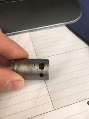
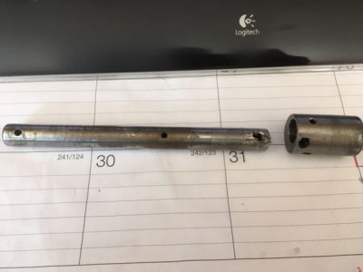
I ordered a shaft and an eccentric from Clausing for my back gears due to the one in the lathe I just purchased looking a bit like Elmer Fudd's gun after Bugs put his fingers in the barrels and it was fired.
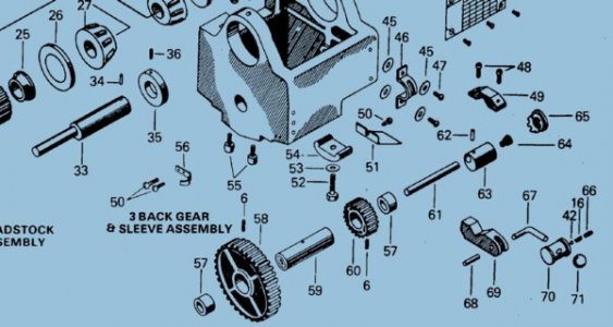
The problem with the new parts is that there appears to be a hole missing where a pin is supposed to go, according to the exploded diagram. (See Back Gears Below) According to a tech at Clausing, they changed the design to eliminate the pin. He couldnt figure why they did that and I am not quite sure why either. I was wondering first if anyone knew if or how the design might work without the pin?
Anyway according to the exploded view there are two eccentrics: No. 33 and No. 63. Each has a hole and a pin (Nos 34 and 62 respectively on the diagram) that is supposed to engage shaft No. 61. A lever clamps on to eccentric No. 63 which rotates the eccentrics and correspondingly moves the back gears out of range of the spindle gears. All seems to figure and would move both eccentrics equally if there were pins or something to lock the shaft in each eccentric.
I can only see that without the pin for eccentric No. 62 the shaft will be free to spin inside the eccentric and only when it binds from being cocked would it tend to spin the other eccentric. This might lead to partial or no disengagement and potentially broken teeth. The Clausing guy is attempting to find the old drawings; he said they may not exist.
So I figured I would ask here. If anyone has run into this issue or the off chance that you might have a diagram showing where this shaft and eccentric is to be drilled for the front pin.
My original shaft looks and eccentric looks like it was drilled in the machine in some haphazard attempt to get the eccentrics to rotate together. The No. 62 eccentric has about 6 holes in it and one time it appears someone tapped it in order to potentially have a set screw engage the shaft.


Last edited:
