- Joined
- Feb 1, 2015
- Messages
- 9,994
Here is a post that might prove interesting to some members. I have a B&D multi-function sander, orbital, finish, detail,etc. that died. Yeah, I know, cheap product not intended to be rode hard and put up wet but it has served me well through fifteen years of remodeling and cabinet making and doesn't owe me a dime. The sander died because the rear bearing froze up and the bearing was bouncing around in the plastic housing and chowdered it resulting in the armature hitting the field core. I was going to chuck it but I have a bunch it pads for it and none of the new sanders that I looked at were muti-functional so I decided to take a stab at repairing it.
To build up the destroyed housing, I decided on using JB Weld. It had to be stronger than the original bearing seat. The plan was to use the motor armature to position the bearing correctly while forming the new seat. I measured the diameter of the armature and the i.d of the core and determined there was a difference of .040". A .020 shim would properly center the armature. I had some .010 aluminum flashing and I heated a piece to remove the temper. It turned out that a second piece was too tight a fit so I salvaged a piece of .006" aluminum from a beer can for a second shim which gave a nice snug fit with no wobble.
The next issue to be addressed was how to make a proper mold for the bearing. A bare bearing would undoubtedly bond to the JB Weld and most likely destroy the new seat when I dissembled it, I thought of using a thin film of grease as a release but rejected that idea as the bearing has negative draft
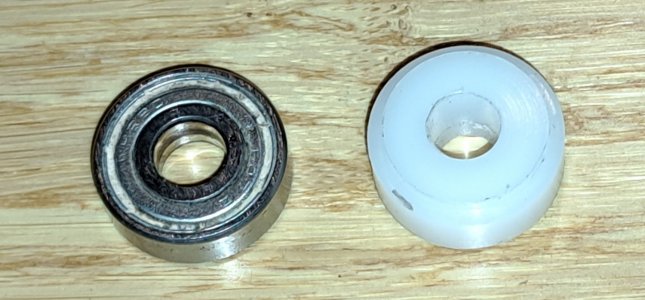
features the would still tend to lock the bearing in place. Then I thought of making a surrogate for the bearing from Delrin since nothing bonds to Delrin and it would be self releasing. The bearing is a 7x19x6 mm. The actual o.d. measured at .7478" or 18.994 mm. The motor shaft measured at .2736" or 6.975mm. The bearing thickness measured at .2355" or 5.982 mm. I turned a section of Delrin rod to .7484" or .0004" over 19mm. There was a gap on either side of the bearing which would have filled with JB Weld so I turned a short necked down region on either side of the surrogate to fill the gaps and prevent the JB Weld from bonding to the motor shaft. I drilled a 6.5mm hole for the motor shaft and enlarged it to 7.0mm which gave an interference fit on the motor shaft. The surrogate was parted off and fitted to the motor shaft.
I cleaned up the bearing seat and removed a little more of the housing to provide some thickness for the JB Weld seat. There were some slots in the housing at the bearing seat which would provide an anchor for the epoxy. I mixed a small amount of JB weld and filled the area, Next, I inserted the motor assembly, using care to ensure the motor field was properly seated. The surplus JB Weld oozed up around the bearing and I carefully cleaned it off and left the assembly to cure. Later that evening, the epoxy had set well enough that the motor assembly could be removed. I cleaned up any residual epoxy and repeated the process on the other half of the housing. After the JB Weld had started to set, I added the first half housing and fastened the two jalv3es together to ensure that the bearing registration between the two halves was good. The next day, I dissembled the housing and removed the motor. There was a very minor amount of cleanup needed to complete the job.
I reassembled the motor and did a short test to make sure that everything was good. Although the directions for the JB weld state that the part could be used after 24 hours, it was still flexible. Epoxy doesn't really cure all that quickly and at the point at which it appears solid, it is only about 10% cured. When I use epoxy, I always make a small test sample to determine its cure state. After 36 hours, the sample was rigid so the repair was deemed ready for use. As I write, my wife is using it to refinish some of our 110 y.o. doors.

Original bearing and Delrin surrogate. The necked down region to prevent epoxy intrusion to the motor is visible. (the black mark is a bit of epoxy remaining on the Delrin after use.)

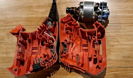
The completed bearing seats with the motor at upper right, ready for assembly. The finish on the new seats is superb.
To build up the destroyed housing, I decided on using JB Weld. It had to be stronger than the original bearing seat. The plan was to use the motor armature to position the bearing correctly while forming the new seat. I measured the diameter of the armature and the i.d of the core and determined there was a difference of .040". A .020 shim would properly center the armature. I had some .010 aluminum flashing and I heated a piece to remove the temper. It turned out that a second piece was too tight a fit so I salvaged a piece of .006" aluminum from a beer can for a second shim which gave a nice snug fit with no wobble.
The next issue to be addressed was how to make a proper mold for the bearing. A bare bearing would undoubtedly bond to the JB Weld and most likely destroy the new seat when I dissembled it, I thought of using a thin film of grease as a release but rejected that idea as the bearing has negative draft
features the would still tend to lock the bearing in place. Then I thought of making a surrogate for the bearing from Delrin since nothing bonds to Delrin and it would be self releasing. The bearing is a 7x19x6 mm. The actual o.d. measured at .7478" or 18.994 mm. The motor shaft measured at .2736" or 6.975mm. The bearing thickness measured at .2355" or 5.982 mm. I turned a section of Delrin rod to .7484" or .0004" over 19mm. There was a gap on either side of the bearing which would have filled with JB Weld so I turned a short necked down region on either side of the surrogate to fill the gaps and prevent the JB Weld from bonding to the motor shaft. I drilled a 6.5mm hole for the motor shaft and enlarged it to 7.0mm which gave an interference fit on the motor shaft. The surrogate was parted off and fitted to the motor shaft.
I cleaned up the bearing seat and removed a little more of the housing to provide some thickness for the JB Weld seat. There were some slots in the housing at the bearing seat which would provide an anchor for the epoxy. I mixed a small amount of JB weld and filled the area, Next, I inserted the motor assembly, using care to ensure the motor field was properly seated. The surplus JB Weld oozed up around the bearing and I carefully cleaned it off and left the assembly to cure. Later that evening, the epoxy had set well enough that the motor assembly could be removed. I cleaned up any residual epoxy and repeated the process on the other half of the housing. After the JB Weld had started to set, I added the first half housing and fastened the two jalv3es together to ensure that the bearing registration between the two halves was good. The next day, I dissembled the housing and removed the motor. There was a very minor amount of cleanup needed to complete the job.
I reassembled the motor and did a short test to make sure that everything was good. Although the directions for the JB weld state that the part could be used after 24 hours, it was still flexible. Epoxy doesn't really cure all that quickly and at the point at which it appears solid, it is only about 10% cured. When I use epoxy, I always make a small test sample to determine its cure state. After 36 hours, the sample was rigid so the repair was deemed ready for use. As I write, my wife is using it to refinish some of our 110 y.o. doors.

Original bearing and Delrin surrogate. The necked down region to prevent epoxy intrusion to the motor is visible. (the black mark is a bit of epoxy remaining on the Delrin after use.)

The completed bearing seats with the motor at upper right, ready for assembly. The finish on the new seats is superb.
