- Joined
- May 17, 2012
- Messages
- 105
I recently purchased a Craftsman horizontal mill, model 101.15500, serial number SM 000626, and it is missing a few pieces. The first one I was planning to make, as it seems to be a simple lathe/vertical mill project is the draw-in bar for the MT2 tapers. I saw a lot of pictures of the bar on the web, but the only drawing I could find that was identified as an Atlas draw-in bar is substantially different from the pictures.
I found the discussion in this thread ( http://www.hobby-machinist.com/threads/atlas-horizontal-mill.21602/page-4 ) but I couldn't find a drawing in the files section that was of that bar. So I created one of my own.
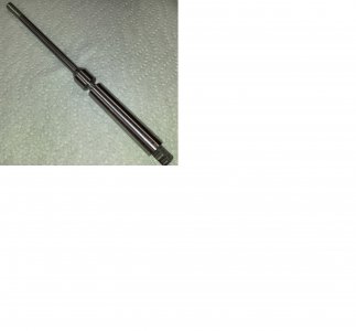
I used VSAcona's photograph of the draw-in bar and put it into Paint. I then drew lines on each of the dimensions and got the pixel counts down in the bottom bar. Since I knew that the small shaft was 3/8, I could then correlate the pixel counts to dimensions. In most cases, they came quite close to regular fractions. I combined these measurements with VSAcona's measurements and made a drawing from this combined data.
The dimensions I calculated are significantly different from the dimensions on the non-standard drawing in a few places.
I've attached a .pdf with the two drawings. Would someone who has an actual factory bar please check the critical dimensions on my drawing? Or if someone has a drawing of the bar on the bottom of the attached .pdf, would you send it along? The one I'm really curious about is the length of the cylindrical part of the 'bearing', which also controls the diameter at the end of the taper. I realize the number of decimals is ridiculous, but it's so that fractions work out.
Once everything is correct, I'll post it in the files section.

