Atlas/Craftsman 618 Bearings Shot?

DaveBarbier

Registered
Registered
Joined
Feb 14, 2016
Messages
121
Hi, first, I hope this is in the right place. If not, forgive me! I've had this little thing for about a year and I have really barely used it. Just recently I did some work on aluminum and it performed quite well. Turning steel makes a pretty bad grinding noise and I can see the work deflect as I make a pass on it. I assume the work is deflecting and not the tool.

Today I was working with some aluminum again. Here's a picture of the setup:
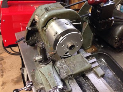
618 with headstock trouble.jpg

I was reducing the OD of this plate and as I was making chips that same bad noise came back and then the lathe stopped turning. The motor was spinning and the belts were moving but the head stock(?) wasn't moving. I shut it off and was able to spin it by hand. I turned it back on and it worked for a bit but then kept stopping on me. It wasn't binding on the cutting tool; it would even do it if I wasn't making a pass.

I just would greatly appreciate some help getting this thing in nice working condition. Just a couple days ago I ordered the tooling kit from the little machine shop with the QCTP, drill chuck and various tooling for about $200. I was using old tooling that came with the lathe this whole time. So I'd like this little lathe to work for me :)

I think I need new timken bearings but am unsure what to get. Or maybe my belt tension is way wrong?

And help is appreciated! If you need more info let me know!

Thanks,
Dave
 
Last edited by a moderator:
Dave,

First, I fixed your photo by finding the URL, downloading the JPG, and then uploading it from a computer. We have a lot of issues with Tapatalk.

Your problem sounds like something other than bearings. The most likely culprit is that the Direct Drive pin slipped out of the hole in the spindle cone pulley and the grinding noise that you heard was the end of the pin chewing up the hidden face of the pulley.

Do not turn the motor on again until you resolve this. If you do not have a parts manual on the 618, first read the instructions for using DOWNLOADS that you will find in the Sticky area at the top of this forum. Then go to DOWNLOADS, navigate to the Atlas Lathe Manuals folder (Category) and download the 618 manual whose name ends in "1950 Rev 2". In the manual, go to the bottom of page 6 page and study the exploded view of the spindle. The direct drive pin is part # M6-256. It fits into the front of the M6-241 Spindle Back Gear (AKA Bull Gear). Lift the belt cover. Rotate the spindle by hand by turning the chuck until the end of the pin comes into view and stop it at about TDC. Check whether the #8-32 set screw is still in the OD of the gear. If it is, check that it is turned down slightly below flush between two adjacent gear teeth. If the set screw is missing, fish in the hole for the spring and ball. They will probably be missing. If they are, try to locate them and the set screw in the bottom of the headstock and under the headstock, including on top of any bed webs under the headstock. Also check in the teeth of the small back gear.

Once you have the set screw, spring and ball in the bull gear, press in on the end of the pin while you slowly rotate the cone pulley. When you find the hole, try to press the pin into it. I don't know exactly how far in it should go but would guess about 3/16" to 1/4". Some pulleys have two holes @ 180 deg.

If you can't get the pin to go into either hole, your only option will be to pull the spindle and repair the pulley. Return to DOWNLOADS and get the Atlas Technical Bulletin on the 6" headstock and follow its instructions.
 
Last edited:
Thanks a lot for the reply. And sorry about the image, it looked fine on my end, not sure what you were seeing!

I do have an exploded view and see M6-256. It's number 123 in the diagram. I see that on my lathe and it's fully seated and I can pull it out and push it in (if it's located correctly) with ease and seems to lock as it's supposed to. I also see the set screw on the largest pulley that's right next to that gear and it's all in there and is slightly flush, as you mentioned.

Now, I have turn the lathe on since it stopped spinning. Probably not a good idea, but I felt that it spun freely by hand so I went for it.

Here are some pictures and a video I just shot. Using imgur instead of tapatalk. Hope it works out.

http://imgur.com/VDonmGW
http://imgur.com/xcX8JgE
http://imgur.com/hY51MbO


Hope this answers some questions. I'm guessing that the pins you're talking about are functioning properly. Next steps?

Thanks a lot!
 
Just a thought from looking at your first picture -- you're not running the cross slide into the work are you? Tough to tell, but the diameter of the aluminum looks very close to the guard on the cross slide, and as embarrassing as it is it's quite possible to do.

I'd also watch how your pulleys run on the motor as well as on the countershaft. Sometimes if they slack off a bit on the shafts they can run against the casting making for a god-awful noise and not always the first thing we look at.

-frank

On second thought any rubbing of the pulleys wouldn't stop the spindle, so forget that idea. -f
 
Dave,

I'm embarrassed that I wrote M6-243 (the back gear assembly) when I meant M6-241 (the bull gear). I corrected it in my original post. But the M6-256 Pin goes into the M6-241 bull gear, not the back gear. Where is is located on the drawing is a little misleading. Perhaps there should be an arrow point to where it goes. And incidentally, the set screw on the back gear assembly M6-243 that you pointed out in the video is the oil filler plug. The one that is in the spindle cone pulley is also an oil filler plug (see last thread in the sticky area above). The screw that I was referring to was the one in the bull gear that you pointed out last.

Well, so much for that theory. My next thought was that the back gears are misadjusted to the point where they just touch the spindle gears, which would cause a racket for sure. But looking at the tips of the teeth of the bull gear in your video and photos, they don't show any signs of having been hitting the teeth on the small end of the M6-243 behind the spindle. Nor do the teeth on the small and large gear just to the left of the belt visible in your 2nd photo. So that isn't it. The compound or cross slide hitting the work piece as mentioned by Frank is another possibility but I don't see any damage to the work piece, and in the various photos, there does appear to be adequate clearance. I assume that the lead screw gear train is in neutral so the noise wouldn't be from there. That does seem to leave the bearings as the culprit, although I would expect them to be noisy all of the time, not intermittently. If I think of anything else, I'll let you know.

On the photos and video, the video is fine. The photo in you first post was showing as just a red "X" when I first looked at your post. When I opened the post for editing, the photo appeared. And opened another way, I could see the URL. That's how I was able to find and download the photo.

The three photos in your most recent post only show the URL to me. Clicking on them does show them but only one at a time. We realize that using a URL doesn't take up any significant space on the site's server. But that method depends upon the URL always being valid. If the site where the file was stored ever goes away or the OP deletes the file or their account or etc., all that shows up is a red "X". Which is irritating to many members. The site owner and a few of the moderators just finished tracking down and deleting over 4000 red "X"'s site-wide, a process which cost us several man-days. So please use the UPLOAD A FILE button available at the lower right of the composing area. We really don't care how any other site does it.
 
Just a thought from looking at your first picture -- you're not running the cross slide into the work are you? Tough to tell, but the diameter of the aluminum looks very close to the guard on the cross slide, and as embarrassing as it is it's quite possible to do.

I was very careful to set up the piece. It definitely wasn't hitting. But that is, for sure, not out of the realm of possibilities for me being so green at using a lathe :)

Dave,

I'm embarrassed that I wrote M6-243 (the back gear assembly) when I meant M6-241 (the bull gear). I corrected it in my original post. But the M6-256 Pin goes into the M6-241 bull gear, not the back gear. Where is is located on the drawing is a little misleading. Perhaps there should be an arrow point to where it goes. And incidentally, the set screw on the back gear assembly M6-243 that you pointed out in the video is the oil filler plug. The one that is in the spindle cone pulley is also an oil filler plug (see last thread in the sticky area above). The screw that I was referring to was the one in the bull gear that you pointed out last.

...

On the photos and video, the video is fine. The photo in you first post was showing as just a red "X" when I first looked at your post. When I opened the post for editing, the photo appeared. And opened another way, I could see the URL. That's how I was able to find and download the photo.

The three photos in your most recent post only show the URL to me. Clicking on them does show them but only one at a time. We realize that using a URL doesn't take up any significant space on the site's server. But that method depends upon the URL always being valid. If the site where the file was stored ever goes away or the OP deletes the file or their account or etc., all that shows up is a red "X". Which is irritating to many members. The site owner and a few of the moderators just finished tracking down and deleting over 4000 red "X"'s site-wide, a process which cost us several man-days. So please use the UPLOAD A FILE button available at the lower right of the composing area. We really don't care how any other site does it.

Roger that about the pictures. I'll use the upload file feature from my computer next time.

So, if the bearings do need replacing, how do I find out which bearings to get? I see the part numbers are M6-81B and M6-82B. Does that help me? Or do I just need to disassemble and read the serial numbers off the bearings themselves?

Thanks for the help!
 
Dave,

We don't appear to have the Timken numbers for the 618 spindle bearings. Clausing still carries them so they won't give out that information. I did find a Clausing drawing that gives the Timken number for the M6-81B. They are 7100 Cone and 7196 Cup. And the drawing says that they should be Class 2, which is the garden variety Class. So they will not be marked with a Class. The bearings in the 10" and 12" were probably Class 3. Which are more expensive.

I'll post a note to the Yahoo A_C Group and the Atlas_618 Group and see if anyone has that information.
 
Oh, so if Clausing carries them then I'll be able to buy them through them? I did a search for M6-81B and found this link.
http://www.searspartsdirect.com/cra...81B/0009/101/model-10115500/0247/0754000.html

It only shows the bearing and not the outer race.

I guess I just don't really understand. In order to buy the appropriate bearing we need the number that the other groups you mentioned may have?

And, maybe a dumb question, but it looks like the two bearings are identical, just rotated 180° from each other, right?

Thanks so much for the help!

P.S. I just got my LMS order of the tool kit with QCTP and drill chuck and such, I can't wait to get this little lathe working properly!
 
Sorry for the delay.

If you buy the bearings from either Sears or Clausing under the Atlas part number, you should get both cup and cone, as that's the way that Atlas always sold them. If you buy them anywhere else, you will need the Timken numbers, and buy the cups and cones separately.

I am still trying to track down the correct 4th part number. The cups are the same at both ends, Timken 07196. The cone on the right end is 07100. Two different sources have given two different numbers for the cone on the left end, 07087 and 07079. Both fit the 07196 cup. But the ID's are different. I finally managed to download the current Timken catalog and confirmed the cup to cone fits and got the cone ID's. Now I just need to find someone who has a spindle loose who will mic the diameter in the area where the left cone fits. In case you go ahead and pull your spindle, the ID's of the two cone numbers are:

07087 0.8750" (7/8")
07079 0.7874" (20 mm)

Probably, considering the year and location of whomever picked the bearing in 1936, it is the first one. But considering what they cost, you wouldn't want to buy the wrong one. Of course if you pull the spindle, you should be able to read the numbers off of the bearing parts.

On a related subject, I am also trying to ID the mill's left bearing. The right one is the same as the right one on the lathe. But the left one's Atlas part number is M1-82B instead of M6-82B. Parts lists dated between 1942 and 1962 all give the same number.
 
Please, no worries!

So I totally understand now. I can see there are "kits" from Timken that includes 07196 and the other cone part numbers you mentioned.

I just assumed that replacing bearings in these things is normal and that you guys have links or part numbers already archived. I guess since you don't then it's fairly rare to have to replace them?

Which brings me to another note. I looked over my lathe and put it on a slow speed and turned it on and it ran very smooth. I didn't want to chuck any work up in it yet and see how making chips goes, but I might do that today as a test. Maybe I'll record it and post the video here so if it acts up you'll see what happens.

Thanks for all the help
 
Back
Top