Are any Rules How to Feed / Lock Axes?

oskar

Registered
Registered
Joined
Nov 24, 2013
Messages
268
I did my first cut today with my Taig mini lathe and although the results were good to my opinion, there are some questions I have regarding how we feed the stock and lock axes

For clarification, I consider the Z axis is moving the carriage left / right, X axis is moving the cross slide front to back and Y axis is moving the mill attachment UP / DN.

When the width on my cut is more than my end mill (in this case the end mill is 0.25” and final width of cut is 0.377”) is it ok to have the X axis unlocked and as I go UP/DN doing the cut with my Y axis also move the X axis front / back to complete the cut across the 0.377” surface?
 
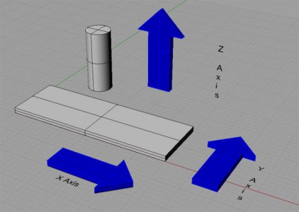
Hi Oskar, I think it would be more clear if we agree on terms. The Up and down axis is usually consider the Z axis. Left and right is X and front to back is Y.

I only mention this so that when folks reply and we ultimately attempt to help it will be consistent with conventional practice.

I am trying to figure out what you are asking and am getting a tad confused.

David
To and from the spindle along it's rotational axis is Z
The major cross axis 90 degrees to Z is X.
The minor cross axis 90 degrees to Z is Y.
That is the standard, long held convention. It all relates to the spindle axis.

Using that language, a vertical mill like a Bridgeport has Z up and down, X left and right, and Y closer and further away. A horizontal mill that looks somewhat similar has Z toward and away, X left and right, and Y up and down. A surface grinder has the same nomenclature as the horizontal mill, because it is laid out the same as a horizontal mill in reference to the spindle.

That said, with CNC machines, which may have many axes, that might move in any direction and orientation, and with many people thinking the Bridgeport mill orientation sets the standard for left/right, up/down, and closer/farther, people are calling axes anything they want, using techie sounding letters, but leaving people misunderstanding what they are describing.

I, personally, am currently making an attempt to not use those letters at all any more. I am using descriptive terms like up/down, left/right, closer/farther, toward/away, and in/out.

The common goal is communication. If we all individually invent our own languages, it is very difficult to communicate...

Standards are put in place for really good reasons.
 
Last edited:
Indeed, Z is always the axis of the spindle. In the case of manual mills, the most common convention is shown as this and the interpretation is the movement of the cutting tool relative to the bed. Not the bed relative to the cutting tool. This is a huge point of confusion.

MillAxes.jpg

To the OP: I assume you are talking about a mill because you mentioned "Lathe" in your opening question. Assuming we're talking about a mill, I lock the various axis based on how heavy the cut is and if the cut is the final pass where precision is most needed.

There are no absolute rules. It depends on your style of doing things and how your equipment behaves given the material and cutting tools at hand.

Ray
 
I’m sorry folks for the confusion but since I’m a beginner on lathes I read quite a few manuals and my understanding regarding the axes is what I mentioned. One of the .PDF I read is the “Hass Automation 2015 Lathe Series Workbook” and on page 8, “The Coordinate System” describes what I mentioned. No point to argue with you since I lack the experience and that’s why I mentioned in my post “for clarification” because I know axes identification is a confusing subject.

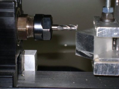
Back to my subject: the attached picture shows the setup at the beginning of my cut. The stock is a 1” aluminum cube and I will cut the 4 corners at 45 degrees. To do the cut I raise the stock UP while the motor is ON to do my first pass, then turn the motor OFF, lower the stock again and advance it to my left a bit and I raise UP the stock again with the motor ON. Then I repeat until the surface of the 45 degrees is 0.377”.

At the beginning the surface of the cut at the corner is less than 0.25” but as I progress the cutting the surface become wider than 0.25” and at one point I have to move the stock back and forth so the end mill will clean all the surface. My question was is it ok to move the stock UP and DN as well as toward the front / back while the motor is ON?

15A First Cut.JPG
 
Oskar, I believe that you are correct in your labeling. On the lathe the z axis is the direction the carriage moves since it is parallel to the spindle. The x axis is the direction the cross slide moves. Normally there wouldn't be a y axis but since you are asking about a milling attachment, it is the direction of vertical movement of the milling attachment.

I would expect the there would be no problem moving your workpiece along any axis while the motor is on. If you are cutting along one axis, you will have best results lock the other two axes.
 
Why cannot we just call their names by what they do; on a lathe there is carriage feed and cross feed, on a horizontal mill there is table feed and saddle feed and vertical feed; on a Bridgeport type mill there is the additional quill feed.
Back in the day when I was in my time, nobody knew anything about "alphabet" feeds. Get back to basics!
 
As I understand it, your explanation of axis designations was correct and in agreement with Bob's and Ray's explanation. No apology needed.

Regarding your basic question, I guess I try to set up to move the work piece through the cut using the most stable axis available and I think it's good practice to lock the axes that are not intended to move.
In your situation, I might move the X axis toward me until the work piece was clear of the cutter then set the Y axis height and Z axis for the first cut, then lock Y and Z. Then traverse X away through the cut, readjust Y for second cut and lock Y then traverse X toward me through the second cut. Repeat as necessary. Unless I thought there was a safety hazard associated, I wouldn't stop the spindle during the adjustments. A safety hazard might include the use of tools or body parts in close proximity to the cutter.
 
Last edited:
As I understand it, your explanation of axis designations was correct and in agreement with Bob's and Ray's explanation. No apology needed.

Regarding you basic question, I guess I try to set up to move the work piece through the cut using the most stable axis available and I think it's good practice to lock the axes that are not intended to move.
In your situation, I might move the X axis toward me until the work piece was clear of the cutter then set the Y axis height and Z axis for the first cut, then lock Y and Z. Then traverse X away through the cut, readjust Y for second cut and lock Y then traverse X toward me through the second cut. Repeat as necessary. Unless I thought there was a safety hazard associated, I wouldn't stop the spindle during the adjustments. A safety hazard might include the use of tools or body parts in close proximity to the cutter.

That's the BEST answer and I understand
Thanks
 
Note that by my method, you'll be cutting "conventional" while moving the part away from you and "climb" cutting while moving the part toward you. Pay attention to the way those cuts are acting and adjust your depth of cut accordingly. Climb cutting is more risky depending on machine stiffness, condition and the particular set up.

Climb cutting can pull the part into the cut, often because of backlash clearance in the lead screw, with undesirable results. Leaving a little drag (lock) on the travel might help. You just have to get to know your equipment and process.
 
Back
Top