Anyone for a real Trestle Bridge?

modela

Active User
Registered
Joined
May 6, 2012
Messages
116
I hike quite a bit on a mountain called Mt. Pisgah. Mt Pisgah is a non-profit organization that maintains over 75 acres with over 16 miles of trails on a shoestring, donated budget.

At a fund raising event I was talking with the manager and offered to volunteer to help on some limited project. Brad said there was an upcoming bridge project and I anticipated a 20 ft. bridge over one of the small streams. "I think I can do that," I responded.


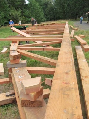
Well, it didn't turn out to be 20'. Here is the bridge project, all 86ft. of it. I worked almost continuously six to seven days per week for four weeks with one to three volunteers on building the bridge. Below is level one. It was built on a grassy slope (somewhat short of ideal conditions) with the bottom laid out.
IMG_0629.jpgsp_Mouse.png
We started with some of the nicest donated fir lumber. The logs were milled at a steam driven mill in Philomath, Oregon. I missed this part, unfortunately. When I arrived on the scene there were a set of engineer/architect plans and that was it. Having a construction background I pitched in and we started from a stack of lumber.
IMG_0743.jpgsp_Mouse.png
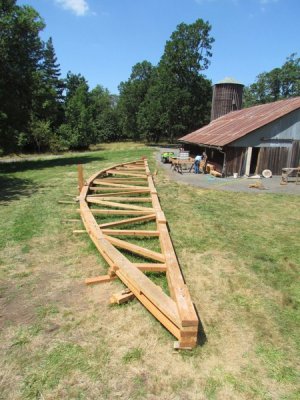
Above shows one side completed. A second side was assembled on top. All holes were drilled and all pieces were labeled and off it went to be pressure treated.
IMG_1359.jpgsp_Mouse.png
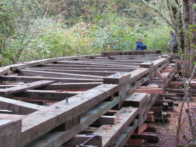
The pressure treating took longer than we thought because it had to be a specially run batch and the wood had to be then kiln dried to prevent the chemicals from leaching into the pond. Back from pressure treating the bridge was assembled adjacent to the pond it was to span. This was a more remote area with a steeper slope. Notice the color change with the pressure treating. I am in the background.
IMG_1374.jpgsp_Mouse.png
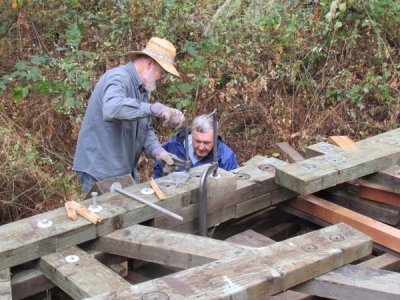
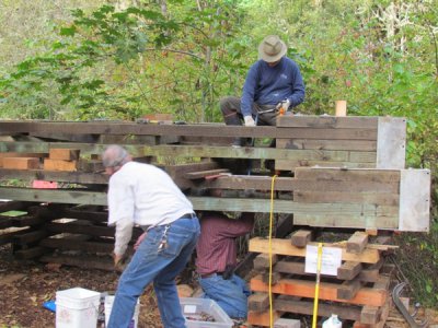
It is a real challenge working with part time volunteers. Fortunately, a friend of mine returned from his months in Europe to help out (on top). I drew the bottom position here attaching the shoes on the ends of the bridge trying to get the holes to line up.
Notice the cribbing supporting the stacked sides. The other end was flat with the ground. We periodically had to level the whole thing as the cribbing was slowly sinking in the mud of the encroaching Oregon winter rains.

Our next job to start this summer (June) is to have a crane lift the two sides, stabilize it and attach the cross bracing and decking.

Jim

sp_Mouse.png

sp_Mouse.png

sp_Mouse.png
 
.......................We periodically had to level the whole thing as the cribbing was slowly sinking in the mud of the encroaching Oregon winter rains. Our next job to start this summer (June) is to have a crane lift the two sides, stabilize it and attach the cross bracing and decking.

Jim

Jim,
That is a great project! Looking forward to the next installment. I hope the next phase scheduled is for June 2012 that just pasted and not next June. Good thing you did not volunteer for buliding it the old fashion way with no crane. All that 86ft span put together piece by piece in place with rope and timbers. That that would be a very long summer project.

Thanks for posting,
Benny

I wrote that in June. I thought things would really be moving but things seem to be bottled up now. To get a good price we have to work with the crane company that seems to be tied up in bigger projects. With volunteers and little money, you can't tell people to "jump".

We do have a volunteer who has worked with bridges in the past. He has also has had a working relationship with the crane company. I took control of the first part but I have never worked with a crane before. I am sure they would have looked at me rather suspiciously.

Jim
 
..............I thought things would really be moving but things seem to be bottled up now. To get a good price we have to work with the crane company that seems to be tied up in bigger projects...................
Jim

Jim,

I know what you mean about having to wait for the crane contractors. I wanted to manage the building of my home so I got the bank to let me be the general contractor. Not an easy task! The project was started when home building and construction in general was very slow in the area. It was no trouble to get contractor help when I needed them. I did a lot of the work myself after work and weekends so it took a while. Near the end of the project construction had picked up and contractors were busy with their regular repeat customers so I was left to wait. A buddy and myself had to do some of the concrete for the walks and steps so I could get an occupacy certificate. Concrete placing and finishing was the last task I wanted to do in the middle of the southern summer.

Just a couple of qestions about the pressure treatment. The color change looks green in the photos. Is the chemical used the copper based material and how much did the treatment mess with your predrilled holes and fit up of all the pieces? The copper based chemical will last forever but you have to be very carefull with any waste.

Keep us informed on the progress. The bridge design is really nice and will be enjoyed for generations.

Benny
 
Benny,

You are right about the copper treatment. We knew that most of the dry rot comes from areas that don't get the treatment and treated it after the holes were drilled. The bridge it replaced was a large glue lam one that rotted out over time.

We had to use a special "eco-friendly" treatment process because this goes out over a pond. That slowed things up because we had to wait until the pressure treating company ran the special batch. In addition we had to have the pieces kiln-dried after treating. That contributed to some of the delays that pushed us into the rainy season last year where we finished soaking wet.

You are right about the holes. We had to ream them all out. In addition we used a special ring system on the joints. All those had to be re-drilled to remove swelled wood.

he biggest problem we had with fit up, would you believe it, was people who tried to put the wrong pieces in place, especially one volunteer. Everything had been labelled--there was no excuse for it. I was going nuts looking out of the corner of my eye while working. We would meet in the morning form a plan and then watch him do his own thing. I caught him at one point getting a chain saw to trim off one of the wrong pieces when it wouldn't fit. I finally assigned a sharp young guy to be what I called the "assembly Nazi." He would alert me when things were going awry.

Fortunately a friend of mine who had a background in construction like I had came back from his 5 month stint in Europe.

I built several jigs to keep the hole drilling true and it was amazing to see how accurately things came out. I will get the pictures of those if you are interested.

Working with volunteers can be a real challenge. I did receive a volunteer of the year award for my efforts.

Jim

Oh, by the way, the area can flood in the winter and go over the top of the decking.
 
Re: Anyone for a real Trestle Bridge? The jigs.

bridgejim.jpg
sp_Mouse.pngSOME JIGS AND OTHER TOOLS.

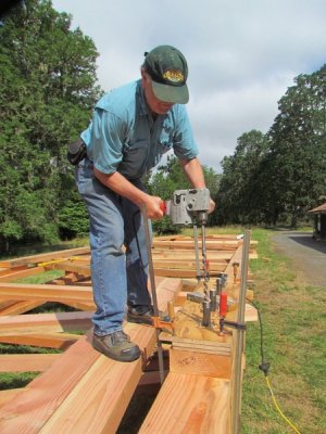
One of the challenges of the Pisgah project was drilling sets of four holes at the joints. There were from one to four 3/4" bolt holes that had to be drilled through five layers of 4x material (18") using a 13/16 bridge auger. The proposal was to drill them individually but I knew that with my drilling the likelihood of them coming out straight was pretty unlikely. I proposed making a jig. My fellow workers thought it was a waste of time and the idea was met with some resistance. It was Friday afternoon and no work had begun so I decided to build the jigs on my own that weekend.

The Jig is made of three layers of 3/4" plywood laminated together. You can see four 1" x 6" black pipe nipples sticking up. These are anchored from below to inset pipe flanges that bolted from the back side. This meant that I had to re-tap the tapered threads from the back side of the flange so that the pipe nipples could stick up through the jig. As a bearing I found that 3/4" PVC pipe would just drive tightly into the 1" black nipple. This meant the drill bit was guided by the close fitting plastic. (see picture where I am drilling the first hole).

The nipple shortened up the depth the auger went in to about 12" deep. We could drill all the holes, remove the jig and bore through the rest of the way. With 12" of straight hole the rest went right through. It amazed me how accurate the holes came out. Some of the joints were only 10 1/2" thick and we could bore through completely using the jig.

In addition I made a 1/2", 4 bolt jig for the upper sections of the bridge

The Ring Boring Tool

IMG_0747-1.jpg
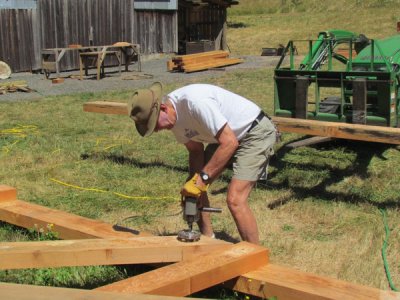
I thought I might provide some tools and techniques I picked up in building the Pisgah Bridge. When you bolt beams together the bolt doesn't give you much contact with the material. For the Pisgah Bridge we used rings to get better contact. The pictures above show how the rings are cut (Milwaukee Hole Hawg and special bit). You can see how they are matched both sides. This is 1920's technology, by the way.

The bit was specially made costing over $900. Fortunately we borrowed it. I sharpened the drill bit three times. It had the oddest configuration of cutting tips. Even more fortunate it had directions and a setting block with it which made it easy to reinstall the sharpened blade.

In operation you really had to watch it because it had a lot of torque. The end of the bit was a guide that kept it straight in the previously drilled 3/4" bolt hole. There were an incredible about of rings to drill. Rob was one of the more skilled volunteers. I was always glad to see him show up. Here he is shown below drilling the holes.


The end of the bit was a guide that kept it straight in the previously drilled 3/4" bolt hole. There were an incredible amount of rings to drill. Rob was one of the better volunteers. I was always glad to see him show up. Here he is shown below drilling the holes.

In the assembly picture you can see in a more detailed way how the joints went together. The joint pictured had eight rings with sixteen grooves cut into the matching pieces. My welding clamps came in handy here. Pressure treating caused a bit of twisting and slight changes which made it a bit harder to assemble. Fortunately we had a good marking system that we etched into each piece with a small Dremel tool.

I think I supplied about three quarters of the tools here, including my beam saw, the Hole Hawg drill, and other hand tools. In addition, I built several jigs including the jig that let us drill four holes at a time with a bridge auger bit.

We just pinned the bridge together through the bolt holes when we first assembled it. The true test came when we had it pressure treated before final assembly. Pressure treating the wood swelled it and we had to go back and ream all of the holes out. There was some twisting and warping of the wood that made some joints a bit difficult. It also made the assembly more critical. Delays in pressure treating forced us into the rainy season.
IMG_1306-Copy.jpg
 
Jim,
very good write up.
Is the intention of the "rings" to only provide friction between the timbers or are they also used for reducing shear on the bolts? Is the depth of the ring grooves that you cut in the timber less than 1/2 the thickness of the ring?
Very interesting, I have destroyed a lot of timber wharves in the past and I have never seen those rings used before.

Cheers Phil
 
Phil,

I believe the rings transfer the shear from the bolts to the rings providing more contact as you have surmised. They were tapered and deep enough so the two frame members made contact. The rings had a slight taper on them and were joined in kind of a finger joint so they could expand somewhat, although the galvanizing seemed to have almost welded them together.

When we built the sides before pressure treating we cut the ring slots but just pinned the pieces together. When we got the lumber back from pressure treating the fibers had swelled and we had to ream them out before assembly. The bolts fit tightly but the precision required to make them fit was more than I expected.

During the assembly we had a few volunteers who liked to beat things into place which I had to put a stop to quickly. I caught one guy who put a ring in both sides and tried to beat it into place. I would say we only had trouble with about eight to ten joints. It was raining when we did our final assembly and our cribbing was settling so we would have to periodically check it and shore it up.

I was told by the architect that these are currently used in Timber Frame construction. We borrowed the jig from a contractor who does some of that kind of work. The ring cutter was an amazing piece, looking like something you would use on a mill. I sharpened it several times and was glad to see there were instructions and a dept setting gauge. The tooth configuration was rather puzzling to me, I suppose to clear chips and to try to reduce the torque required. I wish I had taken pictures of it.

We live near the Oregon coast and I am amazed at the pounding wharves take. Perhaps wharves are bolted together so they have a little give to them, something that wouldn't work with the bridge.

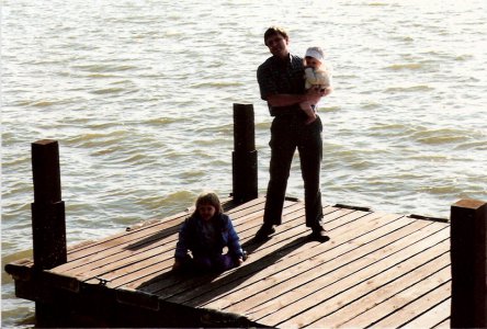
The closest I came to wharves was a dock I built years ago.Fortunately we lived on a lake that was drained in the winter (flood control) which let us set the 6x6 posts. I added 1/2" UMHW plastic to reduce the friction. All the dock did was polish it.
scan0001.jpg

scan0001.jpg
 
Jim,

This to me is one of the best threads on the site.

I love to build things, especially things that allow you to get from one place to another. I always wanted to work on a steam railroad, but NY offers little chance of that. You have to get to Ringoes, NJ or Stroudsburg, Pa to get your hair (or scalp in my case) full of coal cinders.

Seeing this bridge reminds me of the train bridges from the days of steam.

Thanks for posting this.


:tiphat:Nelson
 
Thanks for the comments. I anticipate that we will be setting it in place in the next few weeks. I will try to do a better job taking pictures, especially of the crane work.

When I am in Colorado I will volunteer with my brother-in-law at a railroad museum near Golden, Colorado. Yes, it is right across from Coors and the stench is pretty bad, I am told. The last time I was there we were installing doors he had made on a car that was to be made into a party car for kids. They have a pretty amazing place with a roundtable and many trains and cars. They periodically run a steam train.

There are some trains that run in Colorado and New Mexico that will give you that same ash in your hair.

This is going to be a footbridge over a viewing pond, but boy the feeling of the old days does come back.

Jim
 
Back
Top