- Joined
- Mar 14, 2013
- Messages
- 443
There are a few "treadmill conversion" threads here with varying amounts of information, but I thought I'd summarize my own experiences here in one single thread as I progress. As of this writing, it's still a work in progress:
I've wanted for awhile to convert my Jet 15 mill/drill to a variable speed drive to avoid the hassle of moving the belts around. My shop is so cluttered it's hard to get around to the back of the mill to move the belts. Anyway, a few weeks ago I found a free treadmill... free because the particle board slider bed had cracked but electrically it was in perfect condition.
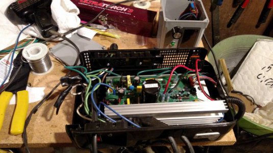
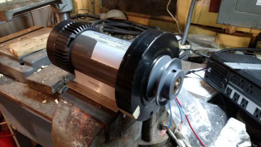
After getting it home and verifying everything worked, I ripped it apart. The motor nameplate says "2.80HP treadmill duty @ 130VDC, 2.60HP cont. duty @ 110VDC/1940 Watts". As my mill has a 1HP AC motor that should work fine. The motor control board, however, is a MC-2100, which is a little trickier to interface than the older MC-60 that only requires a speed control pot. The MC-2100 is expecting a PWM (pulse width modulated) signal from the treadmil control board to set the speed. Fortunately, there are a number of websites with information on how to do this. Warning if you're not reasonably electronics savvy, you'd be better off with the MC-60 or a commercial DC motor controller.
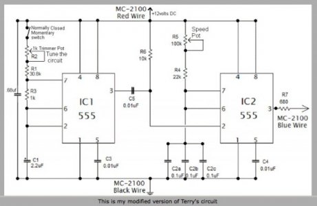
I decided to use the "Sons of Invention" dual 555 timer circuit:
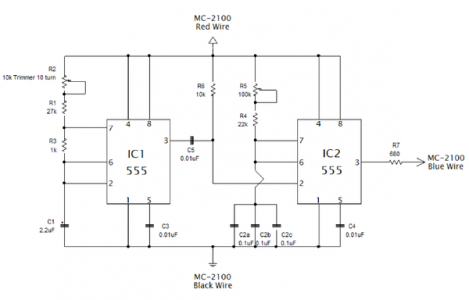
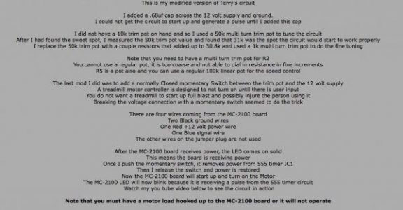
After taking inventory of my electronics junk box, I placed an order from Digikey for everything I didn't already have. Once the order arrived and I had time to play, I put it all together on an old Radio Shack breadboard... and spent most of a day trying to get it to work. Part of my troubles were simple wiring errors, but in the end I had to change a few components. The 27K resistor going to the trim pot didn't do it for me, but a 33K did. I also added an led (with dropping resistor) to the pin 3 output from the first timer. Pointing my old Heathkit "Thumb" Tach (an optical tachometer for model airplanes) at the LED let me check the frequency. I also hooked the 16Hz output (that goes to the blue wire) to a small speaker at one point to verify it was working.
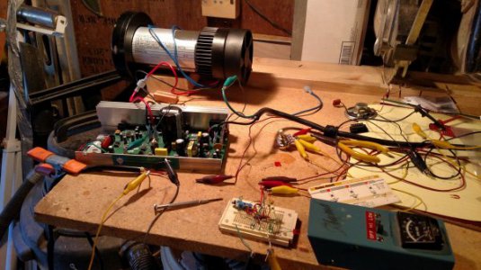
Anyway, I finally got it working, then made a permanent board on a Sparkfun breadboard that was in my Digikey order. Once it was all together, I tested it all... the motor goes from some speed too low for the Heathkit tach to measure up to around 6000 rpm.
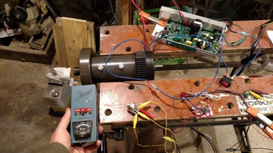
Along the way, I neglected to secure the motor properly so it fell on the floor, shattering the cooling fan... I'll have to work out a replacement.
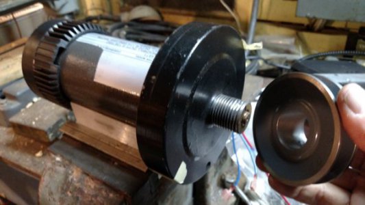
The flywheel / pulley attaches to the motor shaft with a left hand thread. Everything I've seen online makes it sound like it should be a piece of cake to unscrew it. Yeah right. Even with the broken fan removed and the back of the shaft clamped in a vise, it's not coming loose. Although I wanted to remove the flywheel entirely, I don't want to damage the motor trying to remove it, so I'm going to try to use it as it is. The poly-v bent pulley on the motor is roughly 1 1/8" diameter and straight sided, so the plan is to bore out a v-belt pulley to fit over the poly-v pulley.
It's said some of these motors have angled brushes so they'll work better in one direction than the other, but mine appear straight and the motor turns the same speed in either direction.
Part of today was spent hacking up a Tripp Lite UPS case to hold the motor control board and some associated wiring.
I've wanted for awhile to convert my Jet 15 mill/drill to a variable speed drive to avoid the hassle of moving the belts around. My shop is so cluttered it's hard to get around to the back of the mill to move the belts. Anyway, a few weeks ago I found a free treadmill... free because the particle board slider bed had cracked but electrically it was in perfect condition.
After getting it home and verifying everything worked, I ripped it apart. The motor nameplate says "2.80HP treadmill duty @ 130VDC, 2.60HP cont. duty @ 110VDC/1940 Watts". As my mill has a 1HP AC motor that should work fine. The motor control board, however, is a MC-2100, which is a little trickier to interface than the older MC-60 that only requires a speed control pot. The MC-2100 is expecting a PWM (pulse width modulated) signal from the treadmil control board to set the speed. Fortunately, there are a number of websites with information on how to do this. Warning if you're not reasonably electronics savvy, you'd be better off with the MC-60 or a commercial DC motor controller.
I decided to use the "Sons of Invention" dual 555 timer circuit:

After taking inventory of my electronics junk box, I placed an order from Digikey for everything I didn't already have. Once the order arrived and I had time to play, I put it all together on an old Radio Shack breadboard... and spent most of a day trying to get it to work. Part of my troubles were simple wiring errors, but in the end I had to change a few components. The 27K resistor going to the trim pot didn't do it for me, but a 33K did. I also added an led (with dropping resistor) to the pin 3 output from the first timer. Pointing my old Heathkit "Thumb" Tach (an optical tachometer for model airplanes) at the LED let me check the frequency. I also hooked the 16Hz output (that goes to the blue wire) to a small speaker at one point to verify it was working.

Anyway, I finally got it working, then made a permanent board on a Sparkfun breadboard that was in my Digikey order. Once it was all together, I tested it all... the motor goes from some speed too low for the Heathkit tach to measure up to around 6000 rpm.

Along the way, I neglected to secure the motor properly so it fell on the floor, shattering the cooling fan... I'll have to work out a replacement.
The flywheel / pulley attaches to the motor shaft with a left hand thread. Everything I've seen online makes it sound like it should be a piece of cake to unscrew it. Yeah right. Even with the broken fan removed and the back of the shaft clamped in a vise, it's not coming loose. Although I wanted to remove the flywheel entirely, I don't want to damage the motor trying to remove it, so I'm going to try to use it as it is. The poly-v bent pulley on the motor is roughly 1 1/8" diameter and straight sided, so the plan is to bore out a v-belt pulley to fit over the poly-v pulley.
It's said some of these motors have angled brushes so they'll work better in one direction than the other, but mine appear straight and the motor turns the same speed in either direction.
Part of today was spent hacking up a Tripp Lite UPS case to hold the motor control board and some associated wiring.

