- Joined
- Feb 1, 2015
- Messages
- 9,992
Another Lathe TEST Bar
Anyone who regularly follows my postings on HM must realize by now that I am partial the Rollie's Dad's Method for lathe alignment, My weapon of choice is a 1" diameter bar, 15" long salvaged from an old printer. For those not familiar with the RDM method, it is based on the principle that a round bar mounted in the lathe spindle rotates around the spindle axis. If an indicator is brought up to the surface of the bar and the maximum and minimum position is measured, the average of those two measurements is the true position independent of any runout. This is convenient as the bar doesn't have to be straight. It just has to be round.
This means that I can chuck the bar in my 3 jaw. I mount a test indicator on my compound and adjust the tip to be horizontal with the spindle axis. Then I advance the cross feed until the indicator is zeroed. Next, I rotate the chuck and observe the minimum and maximum readings. For convenience, I adjust the cross feed to read zero half way between the maximum and minimum readings.
Next, I move the carriage to the far end of the bar, using care not to disturb the cross slide or compound. Again, I rotate the chuck, noting the maximum and minimum readings. The average of the two readings is my offset.
Some time ago, I realized that the same principle could be applied to tailstock alignment. The only difference that the tailstock center would engage the far end of the bar. If the bar was set up between centers, the bar could be rotated by hand. Ot also limits the measurement distance to the length of the test bar.
My preference is to use my 3 jaw chuck though as using the headstock center requires removing the chuck. A concern with using the chuck is that the chuck most likely has runout and mounting the test bar could introduce stress at the tailstock end with possible errors. To prevent this stress, machined a spherical bushing. The bushing is a slip fit on my test bar and is slit parallel to the axis so tightening the jaws will securely clamp the test bar. The bushing can be positioned at any point on the bar. The assembly is inserted in the chuck and the tailstock center is set to engage the far end of the bar. The chuck is then tightened. Measurement are then made as before.
The advantages of this setup are that the same test be can be used for both basic lathe alignment and tailstock alignment. There is no need for test cuts which greatly speeds up the alignment process. A perfectly straight test bar is not required, expanding the list of suitable bars and eliminating the requirement of verifying the bar truly straight.
For the spherical bushing, I selected a puece4 of 1-1/2" diameter steel of unknown composition. A spark test revealed that it was low carbon and it could be sawed. It came from a collection of drops that were known to contain exotic alloys like A, D and S series steels. The spherical profile was turned first. Then the work was drilled and bored for a slip fit for 1" I errored when cutting the relief on the chuck side of the bushing, cutting it to just under 1" so when I bored the hole, I stopped about .1" short for the last .100" of the diameter. When the hole was properly sized, I slowly increased the diameter of the last .1" until the bushing was parted off. To finish the parted side of the bushing, I mounted it on a 1" pin and used super glue to hold it. I then heated the bushing to break the bond and slipped the bushing off the pin.
I gave the bar a test run to see how it performed. The runout at the chuck was a pleasant surprise. It came in at .0012" TIR. I was really expecting more. Moving to the tailstock, the TIR was .0022" and the offset was .0007". Then I positioned the bushing midway on the bar with similar results. Before I make any correction to the tailstock, I will want to check the lathe ways as that adjustment will impact the tailstock setting.

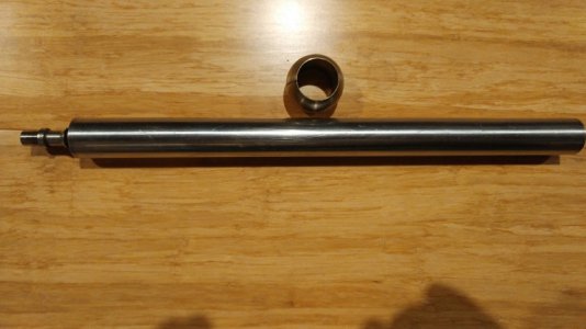
This is the completed bushing and the test bar.

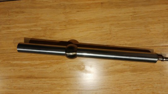
And the bushing on the bar.

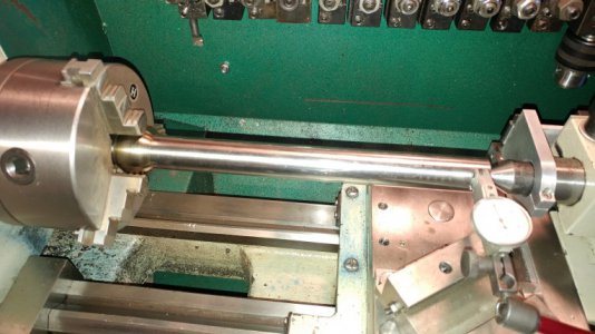
Measuring the tailstock positions at near full bar length.

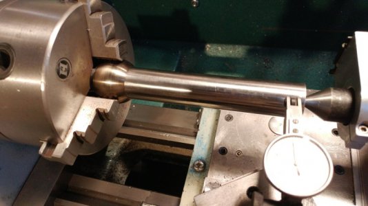
Measuring the tailstock positions at mid bar length.
Anyone who regularly follows my postings on HM must realize by now that I am partial the Rollie's Dad's Method for lathe alignment, My weapon of choice is a 1" diameter bar, 15" long salvaged from an old printer. For those not familiar with the RDM method, it is based on the principle that a round bar mounted in the lathe spindle rotates around the spindle axis. If an indicator is brought up to the surface of the bar and the maximum and minimum position is measured, the average of those two measurements is the true position independent of any runout. This is convenient as the bar doesn't have to be straight. It just has to be round.
This means that I can chuck the bar in my 3 jaw. I mount a test indicator on my compound and adjust the tip to be horizontal with the spindle axis. Then I advance the cross feed until the indicator is zeroed. Next, I rotate the chuck and observe the minimum and maximum readings. For convenience, I adjust the cross feed to read zero half way between the maximum and minimum readings.
Next, I move the carriage to the far end of the bar, using care not to disturb the cross slide or compound. Again, I rotate the chuck, noting the maximum and minimum readings. The average of the two readings is my offset.
Some time ago, I realized that the same principle could be applied to tailstock alignment. The only difference that the tailstock center would engage the far end of the bar. If the bar was set up between centers, the bar could be rotated by hand. Ot also limits the measurement distance to the length of the test bar.
My preference is to use my 3 jaw chuck though as using the headstock center requires removing the chuck. A concern with using the chuck is that the chuck most likely has runout and mounting the test bar could introduce stress at the tailstock end with possible errors. To prevent this stress, machined a spherical bushing. The bushing is a slip fit on my test bar and is slit parallel to the axis so tightening the jaws will securely clamp the test bar. The bushing can be positioned at any point on the bar. The assembly is inserted in the chuck and the tailstock center is set to engage the far end of the bar. The chuck is then tightened. Measurement are then made as before.
The advantages of this setup are that the same test be can be used for both basic lathe alignment and tailstock alignment. There is no need for test cuts which greatly speeds up the alignment process. A perfectly straight test bar is not required, expanding the list of suitable bars and eliminating the requirement of verifying the bar truly straight.
For the spherical bushing, I selected a puece4 of 1-1/2" diameter steel of unknown composition. A spark test revealed that it was low carbon and it could be sawed. It came from a collection of drops that were known to contain exotic alloys like A, D and S series steels. The spherical profile was turned first. Then the work was drilled and bored for a slip fit for 1" I errored when cutting the relief on the chuck side of the bushing, cutting it to just under 1" so when I bored the hole, I stopped about .1" short for the last .100" of the diameter. When the hole was properly sized, I slowly increased the diameter of the last .1" until the bushing was parted off. To finish the parted side of the bushing, I mounted it on a 1" pin and used super glue to hold it. I then heated the bushing to break the bond and slipped the bushing off the pin.
I gave the bar a test run to see how it performed. The runout at the chuck was a pleasant surprise. It came in at .0012" TIR. I was really expecting more. Moving to the tailstock, the TIR was .0022" and the offset was .0007". Then I positioned the bushing midway on the bar with similar results. Before I make any correction to the tailstock, I will want to check the lathe ways as that adjustment will impact the tailstock setting.

This is the completed bushing and the test bar.

And the bushing on the bar.

Measuring the tailstock positions at near full bar length.

Measuring the tailstock positions at mid bar length.
Last edited:
