Another beginner's mistake

twooldvolvos

Registered
Registered
Joined
Oct 19, 2020
Messages
160
I have been working on the slightly painful task of getting together some tooling for my new-to-me lathe. Not painful in searching for the tools, just painful in paying for them. Ha. Ha.

Anyway, here is my latest bad news good news story. I finally purchased a magnetic indicator stand with a plunger-style indicator. That is the good news. So I decided that I should check how tight my old lathe is. I set up the indicator on my 3 jaw. Much to my dismay, I was getting 5 thousandths deflection forward and back by just pushing and pulling with my hands.
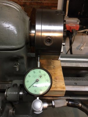
chuckRunOut.JPG

Mind you that I am a green amateur with no one live in person to talk to about my hobby. So now I'm thinking that my spindle bearing must be loose. That's the bad news. 10 thousandths movement just by hand sounds way loose to me. So after a dog walking break I came back to my lathe and started thinking a bit. I grabbed my tail stock and gave it a push and dang. The indicator moved 5 thousandths. Then it hit me. Have you old timers figured it out yet? I had my magnetic base stuck to the chip tray. I was measuring deflection of the tray to the lathe. So I stuck the indicator base to my ways and magically, it only moved about 1 thousandth when I spun, pushed and pulled on my chuck. Back to good news. Looks like its pretty tight after all.
 
Beginner's mistakes - you are not the only one. Raises hand, bashfully. Fortunately, you found your error before doing anything drastic.

Made a little adapter plate to hold a small accelerometer to a small but differently shaped arduino board. Eventually this will be a datalogging orientation sensor. Made a drawing, even entered into a 2D cad program. Spent the morning fiddling around making the plate. Drilled the holes. Deburred everything. Brought the plate upstairs for fitting.

Oops. I machined it faithfully to the drawing, too bad the drawing I made was wrong. I hadn't done a finally sanity check of the drawing against the arduino board - which was sitting on my computer desk, right in front of me. Duh! For some reason, I thought the PWB was 1.00" wide, nope, it was 0.90" wide. Half of the #39 holes I drilled are off by 0.100". Toss this one into the scrap pile. Fortunately, I had made two blanks. Let's just say this was the prototype, right? ;) First, back to the drawing board. Check. Second, confirm measurements on the drawing. Check. Yes, the nut will miss the connector! Yes, the hole spacings are right! Third, and finally, back to the shop...

What's that saying again? Measure twice, cut once?
 
Yup, a good lesson in both frames of reference and relative measurements.
 
Since, what's a mistake without pictures...
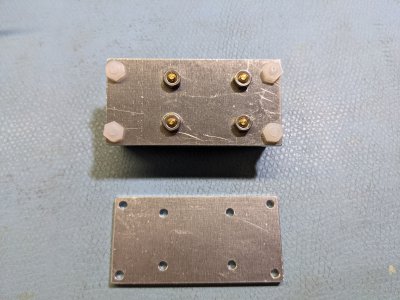
First one, mistake on bottom, assembled good one on top
PXL_20210103_213422275.jpg
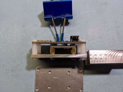
Side view: Have to put some kapton tape on the bottom of the top board to prevent shorts. Accelerometer attached to brass standoffs.
PXL_20210103_213611884.jpg
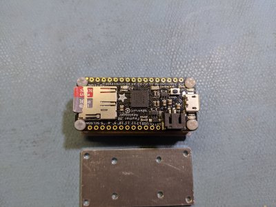
Third view: View of Arduino board. So far, total volume, without battery = 1" x 1" x 2" = 2 cubic inches. Very low clearance on holes, made me go with nylon hardware to avoid shorts.
PXL_20210103_213654137.jpg
 
Beginner's mistakes - you are not the only one. Raises hand, bashfully. Fortunately, you found your error before doing anything drastic.

Made a little adapter plate to hold a small accelerometer to a small but differently shaped arduino board. Eventually this will be a datalogging orientation sensor. Made a drawing, even entered into a 2D cad program. Spent the morning fiddling around making the plate. Drilled the holes. Deburred everything. Brought the plate upstairs for fitting.

Oops. I machined it faithfully to the drawing, too bad the drawing I made was wrong. I hadn't done a finally sanity check of the drawing against the arduino board - which was sitting on my computer desk, right in front of me. Duh! For some reason, I thought the PWB was 1.00" wide, nope, it was 0.90" wide. Half of the #39 holes I drilled are off by 0.100". Toss this one into the scrap pile. Fortunately, I had made two blanks. Let's just say this was the prototype, right? ;) First, back to the drawing board. Check. Second, confirm measurements on the drawing. Check. Yes, the nut will miss the connector! Yes, the hole spacings are right! Third, and finally, back to the shop...

What's that saying again? Measure twice, cut once?
Good advice. It reminds me of the time I made a storm window for my house in my basement. I was ready to take it outside for final fitting and ... I could not get it up the stairs. I had to cut it in half and reassemble it once I got it outside. Then I had the problem that my saw kurf threw my fitment off by just enough to be annoying so I ended up splicing a 1 foot piece into the frame. All was well in the end and I was wiser for the experience. These types of experiences are not taught in text books.
 
The best measuring tools will still only show you what the measurement is. The "skill" part is measuring the right thing. Measuring is like relativistic Physics ala Einstein. Everything is relative to something else and you must pick the correct frame of reference for the measurement you seek.
 
Back
Top