- Joined
- Oct 13, 2012
- Messages
- 175
I'm curious about folks feedback on an idea I just had.
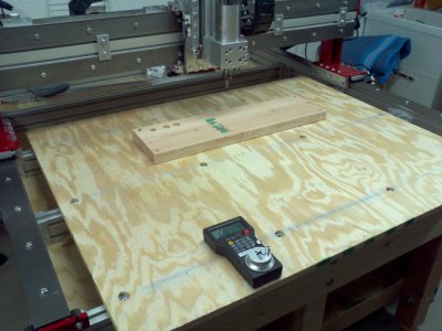
I have a CRP-4848 CNC table that I built. The work area of the table is 48"x48", with the outside extents of the table being (approximately) 51"x60". I have considered many options for work-holding on the table - vacuum, t-slots, 1"x1" hole pattern, etc. At the moment I'm simply screwing the work down. All of these methods require altering the table surface which would need to be replaced periodically.

I saw an article on Hack-a-day [1][2] for a work-holding idea that used two fix mounted carpenter clamps on a small CNC table. This got me thinking about taking four steel bars, fixing two along the y-axis, and two movable along the x-axis and drilling/tapping all of them for 1/4-20 every 1/2". To mount a piece for work, place it on the table and take the x-axis bars and place them "above" and "below" the work piece. Secure the x-axis bars to the nearest y-axis holes, and then use smaller straps locally to finish holding down the work.
This avoids having to modify the waste board at all, and doesn't have to be redone every time you replace the waste board. I would use 3/4"x1" bar stock, I tend to use 3/4" waste boards on my table, so the y-axis bars would be even with the rough table surface.
The only concern I can think of is how much flex would be exhibited on the x-axis bars? Would it be enough to be a problem when milling hardwood, plastic, or aluminum? The Y-axis would secured every 15" inches to the CNC frame, that shouldn't be a problem.
-Freeman
1. http://hackaday.com/2014/03/15/a-different-kind-of-cnc-workpiece-clamp/
2. http://dbugslife.blogspot.ca/2014/03/simple-cnc-clamp-workholding-system.html

I have a CRP-4848 CNC table that I built. The work area of the table is 48"x48", with the outside extents of the table being (approximately) 51"x60". I have considered many options for work-holding on the table - vacuum, t-slots, 1"x1" hole pattern, etc. At the moment I'm simply screwing the work down. All of these methods require altering the table surface which would need to be replaced periodically.

I saw an article on Hack-a-day [1][2] for a work-holding idea that used two fix mounted carpenter clamps on a small CNC table. This got me thinking about taking four steel bars, fixing two along the y-axis, and two movable along the x-axis and drilling/tapping all of them for 1/4-20 every 1/2". To mount a piece for work, place it on the table and take the x-axis bars and place them "above" and "below" the work piece. Secure the x-axis bars to the nearest y-axis holes, and then use smaller straps locally to finish holding down the work.
This avoids having to modify the waste board at all, and doesn't have to be redone every time you replace the waste board. I would use 3/4"x1" bar stock, I tend to use 3/4" waste boards on my table, so the y-axis bars would be even with the rough table surface.
The only concern I can think of is how much flex would be exhibited on the x-axis bars? Would it be enough to be a problem when milling hardwood, plastic, or aluminum? The Y-axis would secured every 15" inches to the CNC frame, that shouldn't be a problem.
-Freeman
1. http://hackaday.com/2014/03/15/a-different-kind-of-cnc-workpiece-clamp/
2. http://dbugslife.blogspot.ca/2014/03/simple-cnc-clamp-workholding-system.html


