- Joined
- Mar 17, 2013
- Messages
- 5
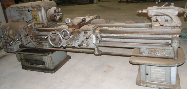
After a four-year project scraping the ways (& otherwise restoring) a 100-year-old Lucas horizontal boring mill (HBM) for the Machine Shop Museum at Tuckahoe, I am now undertaking a similar job on my own 14x54 American Pacemaker -- it is only 66 years old. I thought that the techniques necessary to get both alignment and bearing would be of interest to the readers of this sub-forum. (I am currently discussing the overall project on "another forum", but there are details I am leaving out that might be of interest to folks here.)
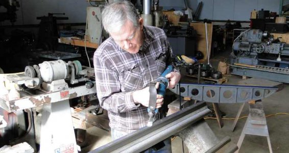
First -- I am not an expert or highly-experienced scraper, but I have been in shops all my life and I am as old as my lathe. I taught manufacturing engineering for twenty years and feel strongly that much of working in a shop is related to having a good mix of experience and theory -- understanding both the "how" and the "why". I am not an efficient scraper, but my experience on the Lucas has given me confidence that I am in control of what I am doing, even if I am slow. Below I am using a Biax power scraper, but for me at the present, alternating hand-scraping with power scraping seems to work best -- both for saving my muscles and for maintaing control on those narrow V-way surfaces:
In order to spot and scrape on a horizontal surface during the many hours of rough scraping, I welded up a sturdy table to support the heavy lathe bed:
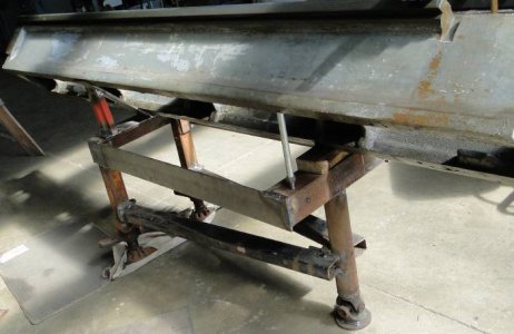
It has two adjustable legs for leveling and can be picked up and moved around loaded using a pallet jack. I will be doing the finish scraping with the lathe bed supported in its normal position. In the center of the pic you can see a jack that allows me to take any twist the bed takes on in this position. I measure the twist using this Starrett level which has been mounted on a B&S magnetic surface gage:
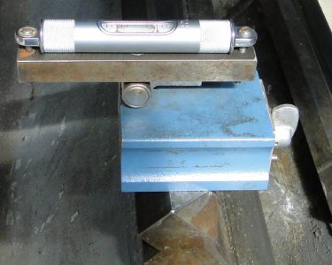
The level also lets me double check that I am not "tipping" the way surface as I do my roughing. So far, my technique with the straight edge seems to be preserving the angle, but I feel better checking as I go along to having to make a major correction later on.
I found that the vertical rear machined surface adjacent to the ways and the top of the ways are possible reference surfaces, I am using this ad hoc measuring tool to measure the progress on scraping the less worn portions of the way surface:
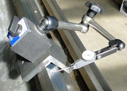
I am not depending on any one reference or kind of measurement, but am measuring several ways and comparing the results. I did spot and lightly scrape on the rear vertical surface and it seems to be a very good reference. The narrow top land is the surface that ATW (American Tool Works) recommends for leveling the lathe and it was planed along with all the other surfaces. I found that measurements using this surface were mostly in agreement with others, but there were small zones where a machinist probably did some light filing to dress off signs of damage to the machine ways.
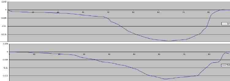
The pic below shows how I did an initial survey of the ways and how I am double-checking the results as I scrape in the second surface of the rear-most V-way pair of surfaces. The V-block is custom-made out of a small piece of cast iron and is scraped to the V-way. The machined surface that the saddle gib sides by without much contact also seems to be a good, unworn reference. (I found this true of the Lucas HBM and my Pacemaker -- it may not be true of more lightly built machines.) My initial survey showed the expected wear zone starting a few inches out from the headstock end, reaching a depth of some .015" about a quarter of the way down the bed, and sloping up from there to an unworn few inches at the extreme tailstock end. The measurements shown above showed the same pattern, but with each way deviating around .010" from the unworn portions. Doing the trig gives a very close agreement.
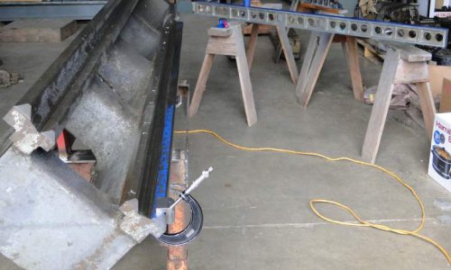
In the background, you can see my six-foot straight-edge. It is a composite piece with the main I-beam made of aluminum with cast iron clad on the working surfaces. I used my five-foot B&S camel-back straight edge to scrape it in -- it is similar to the four-footer in the first pic above. The six-footer actually weighs less than a four-foot cast iron camel-back B&S straight edge.
More detail: When working on each surface, I was presented with around four inches of unworn way surface at the extremes of the 88" length of the carriage ways. This is a classic case of "scraping straight down". I started using shorter (18", 24", & 36") straight edges and although I blued the whole straight edge, (after dressing dings with a fine file) I spotted the straight edge with its center of gravity over the center of area of the unworn land. This printed ink only on the unworn area and as I cycled through spotting and scraping, the area picking up ink grew toward the center. (This depends highly on very consistent and even scraping. I used a very ritualized series of power scraping at 45-degrees left, 45-degrees right, and heavy hand scraping parallel to the way length, each followed by a uniform dressing with a mill file.) Once my six-foot straight edge would span the gap between the end lands, I used it, alternating one end and the other. I was quite pleased at how well this worked -- only very small corrections were necessary as the scraping proceeded. The pic above was taken when there was still about three feet of low area in the middle between the lands. (There is about ten inches of blue at the far end, but it is hard to see in the pic.)
I now will do an "advertisement" for Richard King's Dad's King-way Alignment Instrument. I was fortunate to do my first major machine tool scraping project on a machine that had rectangular ways. I could use a straight edge along, across, and diagonally on the main horizontal way surfaces. Keeping the narrow vertical surfaces straight was easy using a straight edge and measuring the angle with the horizontal ways. The two vertical ways were parallel and near enough to each other that all I had to do was to use a micrometer caliper to measure them directly to keep them parallel.
V-ways are a much larger challenge. There has to be a system to keep the V's parallel -- the Pacemaker has four V's. Many machine tool rebuilders use the saddle and tailstock base from the lathe itself as masters for this operation, but this only keeps them parallel in pairs, so there is still no direct way to make certain that tailstock and carriage way pairs are parallel. This brings me to using a King-way Alignment Instrument or its equivalent -- over the next week or so, I will be making my own version of such an instrument. I will also be making an adjustable test bar, similar to that recommended by Connelly.
In finishing, let me say that I am "working without a net" here, but to use another old saying "it is OK to be in over your head if you know how to swim". If there are any questions or comments, I will do my best to answer, knowing that it will all be in the spirit of the "friendly machinist forum".
Archie
P.S.: To Richard King -- your efforts on this forum were what inspired me to join. Thanks once again for your encouragement.


First -- I am not an expert or highly-experienced scraper, but I have been in shops all my life and I am as old as my lathe. I taught manufacturing engineering for twenty years and feel strongly that much of working in a shop is related to having a good mix of experience and theory -- understanding both the "how" and the "why". I am not an efficient scraper, but my experience on the Lucas has given me confidence that I am in control of what I am doing, even if I am slow. Below I am using a Biax power scraper, but for me at the present, alternating hand-scraping with power scraping seems to work best -- both for saving my muscles and for maintaing control on those narrow V-way surfaces:

In order to spot and scrape on a horizontal surface during the many hours of rough scraping, I welded up a sturdy table to support the heavy lathe bed:

It has two adjustable legs for leveling and can be picked up and moved around loaded using a pallet jack. I will be doing the finish scraping with the lathe bed supported in its normal position. In the center of the pic you can see a jack that allows me to take any twist the bed takes on in this position. I measure the twist using this Starrett level which has been mounted on a B&S magnetic surface gage:

The level also lets me double check that I am not "tipping" the way surface as I do my roughing. So far, my technique with the straight edge seems to be preserving the angle, but I feel better checking as I go along to having to make a major correction later on.
I found that the vertical rear machined surface adjacent to the ways and the top of the ways are possible reference surfaces, I am using this ad hoc measuring tool to measure the progress on scraping the less worn portions of the way surface:

I am not depending on any one reference or kind of measurement, but am measuring several ways and comparing the results. I did spot and lightly scrape on the rear vertical surface and it seems to be a very good reference. The narrow top land is the surface that ATW (American Tool Works) recommends for leveling the lathe and it was planed along with all the other surfaces. I found that measurements using this surface were mostly in agreement with others, but there were small zones where a machinist probably did some light filing to dress off signs of damage to the machine ways.
The pic below shows how I did an initial survey of the ways and how I am double-checking the results as I scrape in the second surface of the rear-most V-way pair of surfaces. The V-block is custom-made out of a small piece of cast iron and is scraped to the V-way. The machined surface that the saddle gib sides by without much contact also seems to be a good, unworn reference. (I found this true of the Lucas HBM and my Pacemaker -- it may not be true of more lightly built machines.) My initial survey showed the expected wear zone starting a few inches out from the headstock end, reaching a depth of some .015" about a quarter of the way down the bed, and sloping up from there to an unworn few inches at the extreme tailstock end. The measurements shown above showed the same pattern, but with each way deviating around .010" from the unworn portions. Doing the trig gives a very close agreement.

In the background, you can see my six-foot straight-edge. It is a composite piece with the main I-beam made of aluminum with cast iron clad on the working surfaces. I used my five-foot B&S camel-back straight edge to scrape it in -- it is similar to the four-footer in the first pic above. The six-footer actually weighs less than a four-foot cast iron camel-back B&S straight edge.
More detail: When working on each surface, I was presented with around four inches of unworn way surface at the extremes of the 88" length of the carriage ways. This is a classic case of "scraping straight down". I started using shorter (18", 24", & 36") straight edges and although I blued the whole straight edge, (after dressing dings with a fine file) I spotted the straight edge with its center of gravity over the center of area of the unworn land. This printed ink only on the unworn area and as I cycled through spotting and scraping, the area picking up ink grew toward the center. (This depends highly on very consistent and even scraping. I used a very ritualized series of power scraping at 45-degrees left, 45-degrees right, and heavy hand scraping parallel to the way length, each followed by a uniform dressing with a mill file.) Once my six-foot straight edge would span the gap between the end lands, I used it, alternating one end and the other. I was quite pleased at how well this worked -- only very small corrections were necessary as the scraping proceeded. The pic above was taken when there was still about three feet of low area in the middle between the lands. (There is about ten inches of blue at the far end, but it is hard to see in the pic.)
I now will do an "advertisement" for Richard King's Dad's King-way Alignment Instrument. I was fortunate to do my first major machine tool scraping project on a machine that had rectangular ways. I could use a straight edge along, across, and diagonally on the main horizontal way surfaces. Keeping the narrow vertical surfaces straight was easy using a straight edge and measuring the angle with the horizontal ways. The two vertical ways were parallel and near enough to each other that all I had to do was to use a micrometer caliper to measure them directly to keep them parallel.
V-ways are a much larger challenge. There has to be a system to keep the V's parallel -- the Pacemaker has four V's. Many machine tool rebuilders use the saddle and tailstock base from the lathe itself as masters for this operation, but this only keeps them parallel in pairs, so there is still no direct way to make certain that tailstock and carriage way pairs are parallel. This brings me to using a King-way Alignment Instrument or its equivalent -- over the next week or so, I will be making my own version of such an instrument. I will also be making an adjustable test bar, similar to that recommended by Connelly.
In finishing, let me say that I am "working without a net" here, but to use another old saying "it is OK to be in over your head if you know how to swim". If there are any questions or comments, I will do my best to answer, knowing that it will all be in the spirit of the "friendly machinist forum".
Archie
P.S.: To Richard King -- your efforts on this forum were what inspired me to join. Thanks once again for your encouragement.


